0
\$\begingroup\$

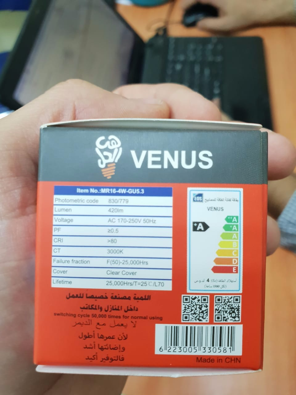
I'm designing a sensor triggered circuit that involves 220 V passing on a PCB, so I designed the board thickness to withstand a maximum of 1.5 A. The main load on the circuit would be a series of LED bulbs, each bulb draws 4 W (says on package). I'm confused on calculating the maximum bulbs I can attach to the load, I'm guessing its one of those scenarios:

Max load = 1.5A / current per bulb = 1.5 / (4/220) = 82 bulbs

Or does the manufacturer calculate power drawn from voltage regulator (5 V) and thus:

Max Load = 1.5A / Current per Bulb = 1.5 / (4/5) = 1.8 bulb = 1 bulb.

added Image

\$\endgroup\$
5
  • 2
    \$\begingroup\$ What 5 V voltage regulator? \$\endgroup\$
    – winny
    Commented Nov 8, 2018 at 12:41
  • \$\begingroup\$ I meant the 5V regulator inside the bulb that steps down 220V AC to 5V DC ( i assume all 220V leds have that built in ) \$\endgroup\$ Commented Nov 11, 2018 at 6:18
  • \$\begingroup\$ It doesn’t. Please don’t assume things when it comes to mains voltage. \$\endgroup\$
    – winny
    Commented Nov 11, 2018 at 6:57
  • \$\begingroup\$ Well, LEDs require only 3V3 so in in its enclosure there must be regulation circuit. bfy.tw/Kntp \$\endgroup\$ Commented Nov 11, 2018 at 7:21
  • \$\begingroup\$ Please do a back of the envelope calculation what the power dissipation would be inside the bulb if your second calculation example would hold true, turn on the bulb, feel the heatsink with your fingers and then draw conclusions. \$\endgroup\$
    – winny
    Commented Nov 11, 2018 at 9:14

1 Answer 1

0
\$\begingroup\$

The power factor (PF) is a keypoint here.

If it was nearly 1.0 then the calculation method you've shown in the original question would be acceptable.

But since it's around 0.5, things change a bit:

Apparent Power = True Power / PF = Power [in Watts] / 0.5 = ~ 2 P

So the apparent power of a bulb will be 8VA. So the current drawn from wall socket will be nearly 8VA / 220V = 36mA

So, if 1.5A is a limit then 1500mA / 36 = 41 bulbs can be connected in parallel.

BUT!

Since the power factor is low, the inrush current (the current drawn for a short time right at the turn-on event) will be extremely high due to the parallelled bulbs. You can fairly estimate 200 Amperes for a few milliseconds. You should also take this into account.

PS: IIWY I would connect max. 10 bulbs in parallel.

\$\endgroup\$
5
  • \$\begingroup\$ That is simply an AMAZING explanation. You paved my way for an unexplored part of my circuitry analysis. Thank you so much for that wonderful explanation. Regarding the 200mA you expect that as soon as they turn on each bulb willl draw that current and thus 1.5/0.2 = (7.5) and thats where the 10 bulbs come from? \$\endgroup\$ Commented Nov 11, 2018 at 6:22
  • \$\begingroup\$ @CcoderBeginner thanks for your kind words. About your question: Please read carefully. When it comes to 230V you should take a lot of things into account. If you connect 41 bulbs in parallel then the inrush current can be 200 Amperes or even 500 Amperes (not milli Amperes). Connecting 10 bulbs in parallel that I've talked about is just about a fairly estimation for safety. \$\endgroup\$ Commented Nov 11, 2018 at 16:20
  • \$\begingroup\$ If you don't mind explaining to me how i can calculate the inrush current for this example to be able to reach a safe conclusion for similar scenarios in the future? \$\endgroup\$ Commented Feb 14, 2019 at 9:21
  • \$\begingroup\$ @CcoderBeginner Well it totally depends on the loads. For example, if the load was an incandescent bulb then the inrush current would be the RMS line voltage (\$V_L\$) over the cold resistance of a bulb (\$R_{cold}\$): \$I_n = V_L / R_{cold}\$. (If more than one bulb were connected in parallel then the total load resistance would be \$R_{CX} = R_{cold} / numBulbs\$). For LED bulbs, since they have a bridge rectifier plus a big reservoir capacitor, the inrush current totally depends on that capacitor. ... \$\endgroup\$ Commented Feb 14, 2019 at 9:58
  • \$\begingroup\$ ... As you might know, a capacitor has nearly zero resistance when it's empty. As the voltage across the capacitor increases, the resistance reaches to nearly infinity. Thus, when you first apply the voltage, the source will see nearly zero resistance (because of empty capacitors). It's not easy to calculate, but you can measure it with a relatively low resistor and oscilloscope. PS: In my LED bulb designs, I always put a series 10R resistor to limit the inrush current so that any fast-acting fuses don't blow. Your loads may have those resistors inside as well. \$\endgroup\$ Commented Feb 14, 2019 at 10:01

Your Answer

By clicking “Post Your Answer”, you agree to our terms of service and acknowledge you have read our privacy policy.

Not the answer you're looking for? Browse other questions tagged or ask your own question.