0
\$\begingroup\$

I'm trying to implement DMX with a Raspberry Pi after reading this page: https://www.element14.com/community/groups/open-source-hardware/blog/2017/08/24/dmx-explained-dmx512-and-rs-485-protocol-detail-for-lighting-applications

I'm using the "RS485 Pi" board.

I've plugged my oscilloscope probes on the UART TX pin of the Pi and get signal 1 (yellow), which lets me verify that timings are good. Next step is to convert to RS485, done by the board. Signal 2 & 3 are the "A & B" output. You can't see the "2" marker, it's under the "3". When UART outputs a 0, I get a nice difference between 2 & 3 (visible in red, which is 3 - 2). But when outputing a 1, I get 2 & 3 to be roughly at the same voltage, so no difference. That does not seem correct to me, I've probed a commercial DMX output and basically, a 1 is like a 0 with A&B signal swapped. Does the signal (2 & 3) below, especially when 1 is high seem correct to you?

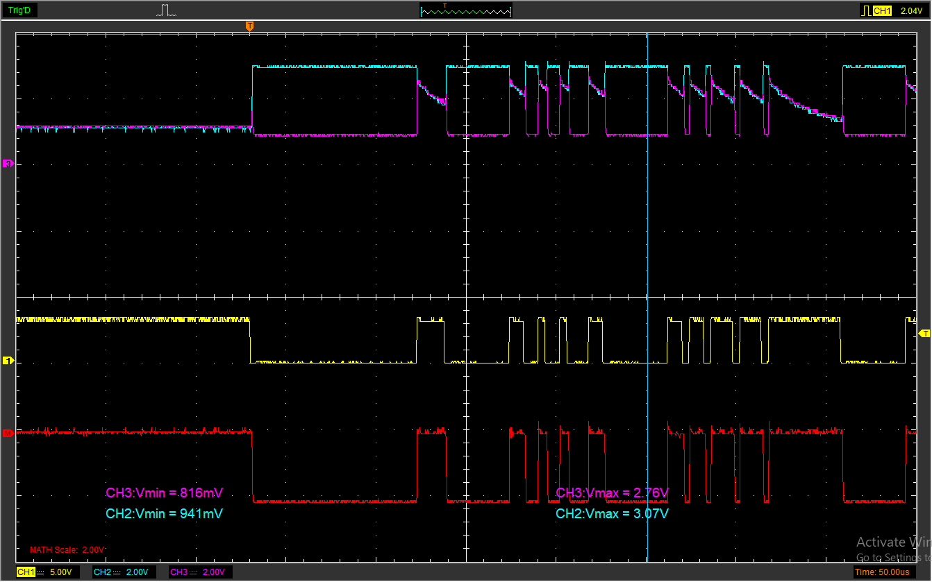
Oscilloscop view

\$\endgroup\$
4
  • 1
    \$\begingroup\$ It looks to me as though you've wired up your RS485 driver incorrectly. Seem like you have its Transmit-Enable pin being driven by the UART TX data, instead of giving it a constant high value during your transmit period. \$\endgroup\$
    – brhans
    Commented Jan 22, 2019 at 13:50
  • \$\begingroup\$ @brhans you're right. The RS485 Pi connects the transmit enable to the data pin. \$\endgroup\$
    – Steve G
    Commented Jan 22, 2019 at 14:06
  • 2
    \$\begingroup\$ @SteveG - Well ok then ... That's an awful arrangement and prevents this board from really doing RS485 correctly. I'd suggest that the OP move R6 over to the empty R7 and drive GPIO17 appropriately to enable/disable the RS485 driver. \$\endgroup\$
    – brhans
    Commented Jan 22, 2019 at 14:20
  • \$\begingroup\$ Thank you very much guys, I actually thought there was something wrong, but when I contacted them they told me it was all within the specs... \$\endgroup\$ Commented Jan 22, 2019 at 16:14

2 Answers 2

0
\$\begingroup\$

That does not seem correct to me, I've probed a commercial DMX output and basically, a 1 is like a 0 with A&B signal swapped. Does the signal (2 & 3) below, especially when 1 is high seem correct to you?

No that isn't correct - it looks like you are feeding the enable pin instead of the TX data line or, maybe you are feeding the TX data line but your enable line is floating.

\$\endgroup\$
0
\$\begingroup\$

I have version 1.0 of the "RS485 Pi" board and it has the same issue. Driving the DE/RE pins high manually for transmit fixes the issue and the A/B lines are clearly inverted producing the correct A-B signal.

Oscilloscope showing the original UART signal and the corresponding A and B lines and their A-B differential

My board also doesn't appear to have the R7 resistor connector to allow using GPIO17 for driving the DE/RE lines programmatically.

\$\endgroup\$

Your Answer

By clicking “Post Your Answer”, you agree to our terms of service and acknowledge you have read our privacy policy.

Not the answer you're looking for? Browse other questions tagged or ask your own question.