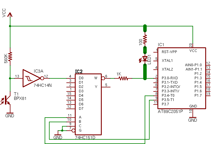
I made a circuit which selects one of 4 sensors and determines if a valid data stream is present on that sensor and counts the number of times data is valid. I narrowed my problems to hardware.
In the original circuit, I did not include the LED and 100 ohm resistor in series (see thick wire in schematic) because I thought I didn't need it. Then I started adding it temporarily and everything seems to run more smoothly with it in.
So at this point with the resistor and LED in, I can detect light status on any sensor of my choice at a rate of 1 every 2 ms. Ideally, I want to detect at a rate of 1 every 125 us.
I believe my problem exists because of some delay caused by the math resulting from the internal resistor on the micro's RXD pin plus the 1k resistor plus a capacitor somewhere in any of the IC's?
The reason I added the 1k resistor is because if by fat chance I ground the RXD pin via software and output W is high and I didn't have any resistor then I'd have a short circuit which I do not want.
But what baffles me is that I get success with the diode and LED circuit even though output W would return a high or low since the part is a 151 not a 251 or does that chip output still have a resistor in series?
My other thought is to replace the AT89C2051 with an AT89LP4051 but that's asking for more money and another programmer.
Anyways, other than my thoughts, Can I configure this setup hardware wise to allow a signal to pass through from the photo transistor to the micro via a multiplexer at a rate of 1 bit per 125us? (like change resistor values and/or add/remove resistors)? etc.
Currently I have the entire circuit minus the LED+resistor in series mounted on a PCB with tracks at least 12 mils wide and power tracks at least 40 mils wide.
The supply voltage averages at 4.8V.
UPDATE
I have tried all of the following without success:
Replaced the series LED+resistor combo in original circuit with just a 1K resistor and used 220 ohm for series resistor
Removed the series LED+resistor combo and instead connected the GPIO pin to ground via 22K resistor and again used the 220 ohm for series resistor
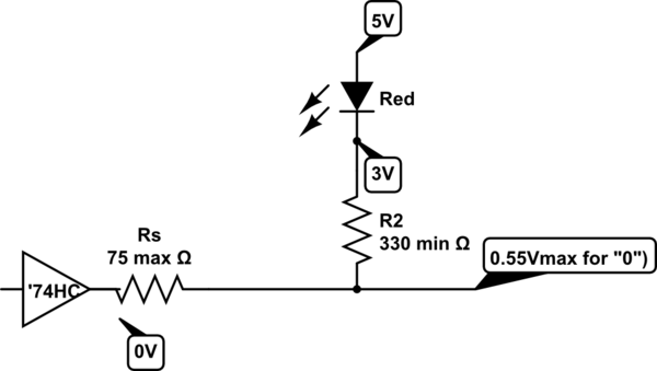
Now I haven't gone as low as 75 ohms for series resistance that someone pointed in their diagram but I'm still a little fuzzy. Maybe there's an entry in a datasheet I need.
Now I'm curious, considering this micro has (based on literature I read) GPIO pins in open drain format only, could I get away with removing the resistors and LED and replacing the series resistor with only one reverse-based diode (so anode connects to GPIO and cathode connects to multiplexer output)? If so, can I get away with a standard 1n4148/1n914 diode?


