2
\$\begingroup\$

I need to measure the overshoot and to modify some capacitor values in the feedback loop of the operational amplifiers in order to find the best response of the power supply (it's a linear power supply).

I am using a GDS1052U oscilloscope from GWInstek.

I am using a switch load made by LM555 and a power mosfet and the signal coming from 555 can be seen on the 10ms/div while the overshoot can be seen only on the 250-500ns/div. I did not found any information for measuring this by using my type of scope. If I use auto settings there nothing appears on the screen.

Please let me know, how to measure this with my scope and what setting should I use?

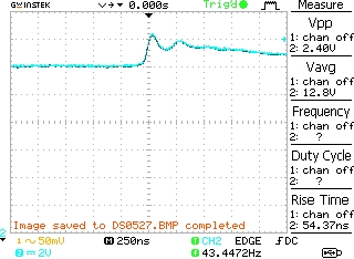
This is the screenshot on 250ns/div enter image description here]1

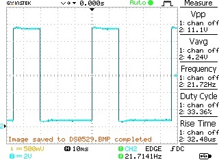
This is the signal generated by the LM555: enter image description here

Why the overshoot can be seen on 250ns/div, while the comutation signal of the load can be seen at 10ms/div?

\$\endgroup\$
5
  • \$\begingroup\$ The overshoot only happens on edges, right? Is there a reason that you can't just zoom in on the edge and not worry about the rest of the pulse? I would think that scope could certainly go down to 500ns/div. \$\endgroup\$ Commented Mar 21, 2019 at 6:28
  • \$\begingroup\$ @Los Frijoles Yes the overshoot happens only ob the edge of the waveform. I do not know how to zoom. Yes the scope goes 500nS/div, but is that normal for the overshoot to appear at 500nS/div while the signal from 555 can be seen only at 10mS/div ? I will upload some images later... \$\endgroup\$
    – beard999
    Commented Mar 21, 2019 at 6:57
  • 2
    \$\begingroup\$ Please do upload schematics as well \$\endgroup\$
    – Huisman
    Commented Mar 21, 2019 at 7:38
  • \$\begingroup\$ I did not found any information for measuring this by using my type of scope. There is none, all scopes behave in a very similar way. Generally the "autoset" option is only useful for "standard" signals like sine- and square waves. Not for pulses like this, you will have adjust the scope manually. Especially the triggering needs to be done right to be able to view the overshoot properly. Do note that at the 500ns/div setting you might be seeing ringing as well. So not the response of the supply's feedback but LC-resonances in your setup. \$\endgroup\$ Commented Mar 21, 2019 at 9:07
  • \$\begingroup\$ Please show schematic and your measurement setup. \$\endgroup\$
    – winny
    Commented Mar 21, 2019 at 13:00

1 Answer 1

3
\$\begingroup\$

Why the overshoot can be seen on 250nS/div, while the comutation signal of the load can be seen at 10mS/div ?

The load commutation signal can be seen at 10ms/div because that timescale is in the range of the event - i.e. you are pulsing the load every 45ms so a 10ms/div timescale is very appropriate.

The overshoot can be seen at 250ns/div because that timescale is in the range of the event - the overshoot lasts for what looks like approximately 1ms so a 250ns/div timescale is very appropriate.

I am going to now attempt to read between the lines to try and glean what you're really asking for:

  1. Why can I not see the transient on the slow time scale?
  2. Why did autoset not set the timescale so I can see the transient?

Answer to 1: The screen resolution of this scope is 320x234 per the product spec. Also, the whole screen isn't available for signal so let's just say for convenience sake that 250 horizontal pixels are available for the waveform. There are 10 graticules, so 25 pixels per graticule. At 10ms/div, that's 25 pixels per 10ms or 250microseconds per pixel. Your 1ms transient event will last exactly 4 pixels, making it very hard to see. We can use similar math for the vertical scale, or just some simple ratios: you changed the vertical resolution from 50mV/div to 2V/div, so the transient would be 40x "shorter" i.e almost impossible to discern. Looking closely at your waveform you can just discern the transient on the top of the pulse.

Answer to 2: Given the choice between large swings (the pulses) and a little bit of fuzz on the top and bottom edges, the scope is deciding that the pulses should be the target for autoset and is making adjustments accordingly. A good way to set up for transients would be to put a rising/falling trigger on the left edge of the scope and go for a fixed time scale (like 250ns/div). Once you can deterministically trigger, you can play with things like holdoff to get the area of interest nicely framed on the screen.
\$\endgroup\$
0

Your Answer

By clicking “Post Your Answer”, you agree to our terms of service and acknowledge you have read our privacy policy.

Not the answer you're looking for? Browse other questions tagged or ask your own question.