1
\$\begingroup\$

I think the title says it most - I was wondering how much bandwidth is needed for the amplifiers within the analogue feedback path of a DC/DC converter?

I am having some issues with my design where the output amplifiers seem to be oscillating, they are OPA656U TI devices and have 500MHz bandwidth and unity gain stable - I am using them as a buffer before a second inverting amplifier gain since my output voltage to be detected is a negative voltage. I am wondering with the bandwidth (and the high output voltage slew rate, too) are causing the oscillation issues in the feedback path.

Does anybody have any recommendations? My switching frequency is 700kHz, but I would be hoping that would be gone by the time the amplifiers seen the DC input voltage due to the capacitors at the output.

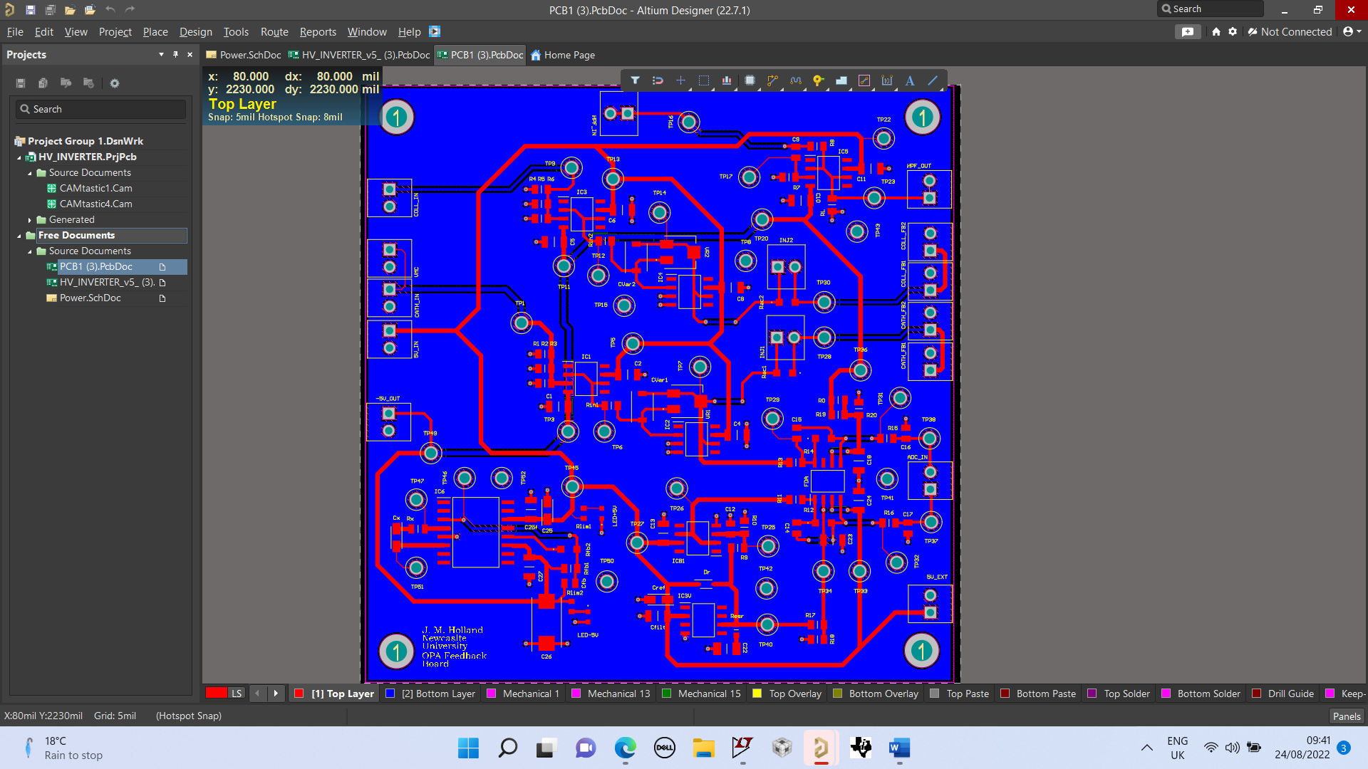
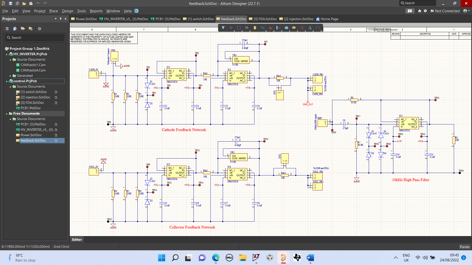
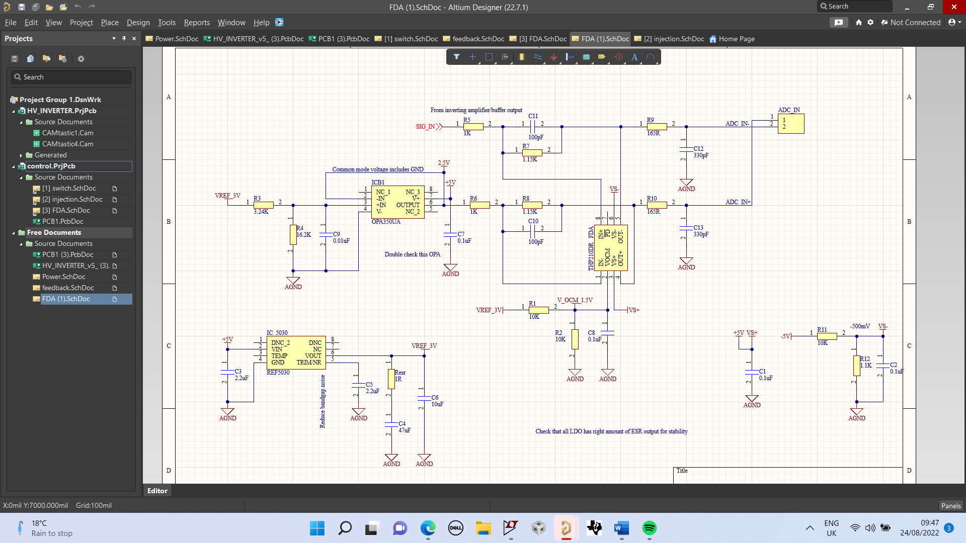
EDIT: I have included the schematic and layout of the operational amplifier feedback board. There is also a fully differential amplifier on board to translate a single-ended source into a differential signal for higher accuracy 16-bit sampling in the DSP, but I haven't got as far as testing that yet since I am having oscillation issues with the buffer amplifier. The ADC's are sampling at 400kHz and 1MHz at the moment. I have a "DNP" capacitor between the inverting amplifier output and negative input pin which I will solder today and see if it improves things. This is a JZ400 and is a 8-40pF variable capacitor. These ranges of capacitors were recommended by TI for compensating for circuit parasitics - but I don't know whether that will be high enough to improve the phase response of the op-amp that is causing the oscillations.

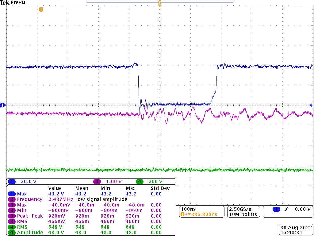
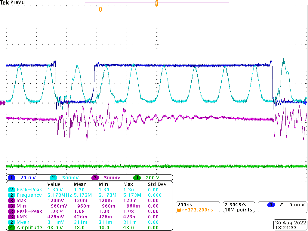
EDIT 2: I will attach a scope screenshot of the oscillations occurring in the 500MHz buffer amplifier output. It can be seen that they align with the switching on of the power MOSFET. Probably the current is ringing and inducing EMI into the other parts of the converter. I replaced the standard wire with twisted pair shielded cable and things look better, but the oscillations still exist. I am hoping that the 2.5MHz operational amplifier eliminate the majority of this switching noise because although the scope is reading it as 2.37MHz it is much higher than this (see purple trace of scope shot attached). The output of the buffer amplifier that goes into the inverting amplifier to scale to 0-3V also oscillates, see light blue trace in the second scope screenshot. I would appreciate any advice on why this is occuring - and would using a lower bandwidth amplifier for the buffer ensure that the oscillations are reduced?

Best regards, J

OPA Feedback Layout

OPA Feedback Schematic

Fully differential amplifier circuit

Yellow (switching VDS), green (output voltage) and purple (operational amplifier buffer output voltage) waveforms

Oscillations in inverting amplifier output, OPA350U, light blue.

\$\endgroup\$
8
  • 3
    \$\begingroup\$ Could you add a diagram of your setup as it's unclear from the text how exactly things are put together. \$\endgroup\$ Commented Aug 23, 2022 at 14:08
  • \$\begingroup\$ Less than 500 MHz for most converters. Do you have any limitations on step response? \$\endgroup\$
    – winny
    Commented Aug 23, 2022 at 14:10
  • \$\begingroup\$ These days a switching supply that uses op-amps in the feedback loop is decidedly oddball. So please edit your question with a schematic -- preferably just a chunk of schematic that shows the switching controller, the output transistors, the output filter, and the output loop. \$\endgroup\$
    – TimWescott
    Commented Aug 23, 2022 at 14:22
  • \$\begingroup\$ Details on the physical construction will help also. Custom PCB? Deviations from recommended layout? \$\endgroup\$
    – rdtsc
    Commented Aug 23, 2022 at 14:38
  • \$\begingroup\$ You could also share the gain on the two op-amp ... \$\endgroup\$
    – Antonio51
    Commented Aug 23, 2022 at 15:16

1 Answer 1

6
\$\begingroup\$

The op-amp characteristics start to matter when you want to push crossover towards high frequencies. For a classical ac-dc adapter where a 1-kHz is sufficient then the op-amp low-frequency pole or gain-bandwidth product (GBW) can usually be ignored. When you start pushing crossover and need to have gain and phase boost at high values like 50-100 kHz in high-speed dc-dc converters for instance, then considering the op-amp characteristics becomes crucial.

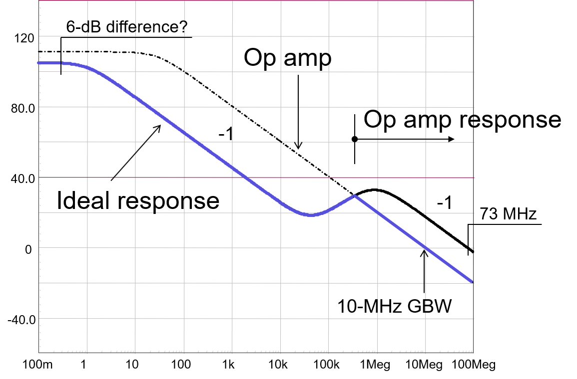
I have looked at the subject in a 2-part series of articles I published in How2Power entitled Understanding Op Amp Dynamic Response In A Type-2 Compensator. Basically, the op-amp open-loop ac response shall not impose its response over the one you want. This is the case for instance in the below graph excerpted from my APEC 2015 seminar:

enter image description here

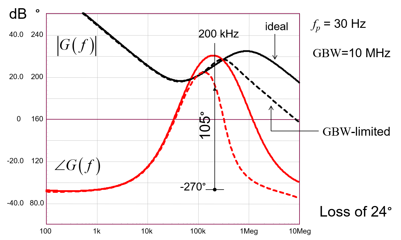
Having this type of conflict will alter the expected response from the compensator and eventually makes the loop unstable. Look at the below plot in which I wanted a significant gain at 200 kHz with a good phase boost:

enter image description here

The gain severely drops past 200 kHz and the phase boost is missed by 24° which is significant because the op-amp is inappropriate for this job.

The slew-rate can affect the loop also but it is more a large-signal issue in this case. I covered the subject in the seminar as well.

The conclusion of the paper and my seminar is that you need to carefully select the op-amp characteristics based on the compensator ac response obtained with an ideal component: the selected op-amp response must "fly" well above that response to limit its impact in the end.

\$\endgroup\$
2
  • \$\begingroup\$ What if you are not compensating a signal but rather just "pre-conditioning" it before it is passed to an ADC? This is a brilliant answer by the way, thank you very much for taking the time to post it. I am using the 500MHz operational amplifier as a simple buffer at the moment, and the second amplifier reduces the DC voltage to 0-3VDC with a low output impedance such that the ADC can properly sample the signal. Any compensation of the converter occurs in a digital controller - would we still expect the above to stand true for digital controllers? I aim for a high controller BW (~50kHz). \$\endgroup\$
    – jvnlendm
    Commented Aug 24, 2022 at 15:01
  • \$\begingroup\$ I have bought some new operational amplifiers with much slower slew rates and smaller bandwidths (2.5MHz and 10MHz) in an attempt to limit the bandwidth of the circuit and thus hopefully remove the oscillations. I am also not entirely sure whether this is coupled EMI from the fast-switching of GaN/SiC MOSFETs/diodes. I bought some Texas Instruments devices with EMI input filtering which should be able to help me understand whether the above is true or not. Will update the forum when I receive them and test them! \$\endgroup\$
    – jvnlendm
    Commented Aug 24, 2022 at 15:03

Your Answer

By clicking “Post Your Answer”, you agree to our terms of service and acknowledge you have read our privacy policy.

Not the answer you're looking for? Browse other questions tagged or ask your own question.