0
\$\begingroup\$

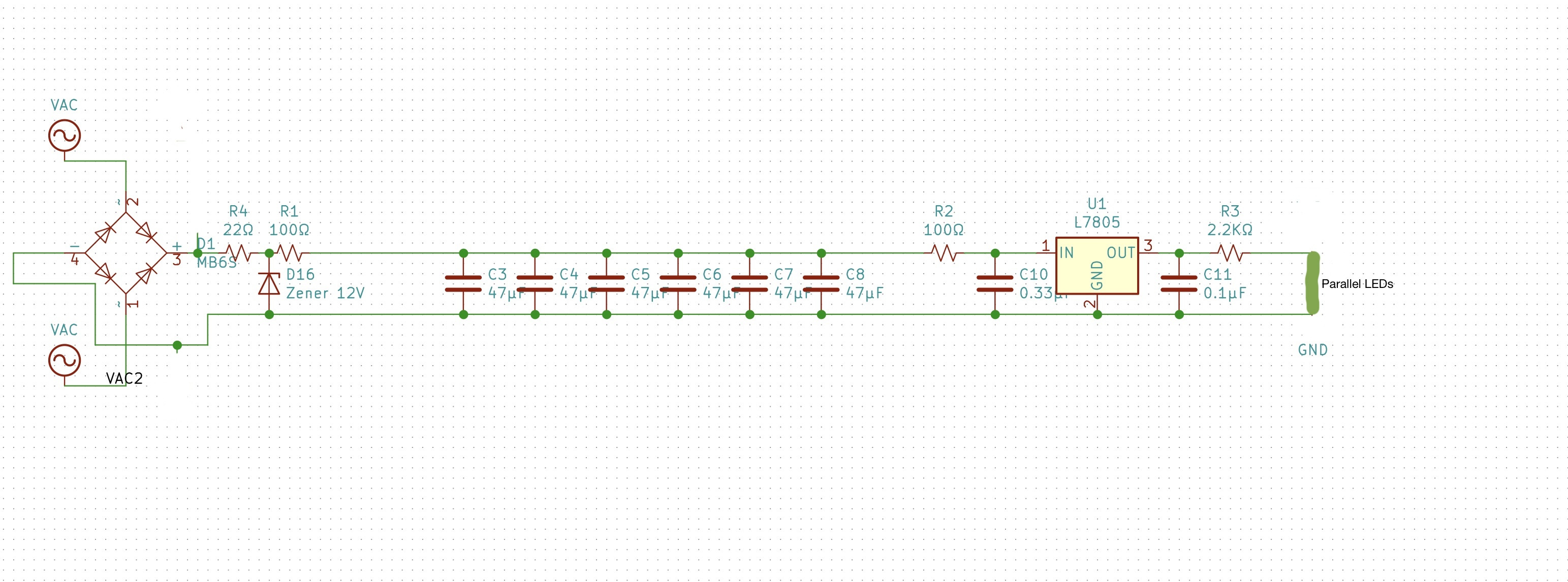
I am a total novice when it comes to electronics. I had a simple circuits class 30 years ago as a software undergrad. I've designed a simple LED lighting circuit for N-scale model railroad, to be used to light passenger cars. The circuit includes "anti-flicker" capacitors so that minor interruptions of input voltage due to dirty track, etc. do not cause the lights to flicker (which is terribly annoying).

I used example circuits from various websites plus input from forum members on an N-scale forum I am on to come up with this circuit. I've mocked it up on a breadboard and it works, but I wanted to make sure it makes sense to people who know more than me. The exact values in the circuit are just an example and I am not sure the resistor leading into the zener makes sense. I've watched a few zener diode YouTube videos and looked at online tutorials.

The goal of the circuit is to have a board made that the user can then populate with their desired components (amount of anti-flicker capacitance, "dimming resistor", number of LEDs in parallel, size of LED, 3.3V or 5V regulator feeding the LEDs etc).

The input is meant to be either DCC track voltage (n-scale levels) which is a digital square wave signal (and represented by the "VAC" inputs and on the output of the rectifier shows as around 13.5--14.5V), or for those using DC analog trains, a positive or negative voltage (usually 0-12V but can be higher than 12V).

So the input is fed through a bridge rectifier, and the output is then fed into the circuit. The main circuit is composed of anti-flicker capacitors that feed a voltage regulator (listed as L7805 but I am using AMS1117 in 5V or 3.3V versions). The output of the voltage regulator is fed into the LED circuit, which has a "dimming" resistor (shown here as 2.2k ohms, and which can probably vary from 750 ohms to around 3k ohms depending on how bright the user wants the LEDs to be, what sort of LED (0805 or 1206 -- the difference being the amount of light they produce so relative brightness of an individual LED to get the desired overall passenger car internal brightness), whether 5v or 3,3v from the regulator, etc.

The capacitors are meant to be SMD ceramic capacitors. While up to 47uF are available in 25V versions, 100uF (in 1206 or smaller or 1210 size) are hard to find in 25V versions (at least economically), but readily available in 12V, so to be able to use 16V versions of the capacitors, I added a zener diode between the rectifier and the capacitors in order to "hard limit" the voltage into the capacitors at about 12V.

(There is also a resistor of 100 ohms or 75 ohms to limit a hard surge of current into the capacitors [as I gathered from other circuits, and a similar low value resistor into the voltage regulator).

It appears from my testing that this is about correct but I am not sure I am computing the resistor leading into the zener correctly.

The zener I have is a ZMM12V (from Chanzon -- inexpensive Chinese stuff as this is meant to be a low cost board) -- https://www.aliexpress.com/store/product/100-500-2500-Pcs-SMD-Zener-Diode-0-5W-12V-ZMM12V-ZMM12-LL-34-SOD/313665_32854074530.html?spm=2114.12010612.8148356.14.711e4cf5y0vwxT

I had computed around 35 ohms based on a 13.5V input and a 12V zener voltage. But this gives me around 12.5-12.7V. If I make this resistor 150 ohms the voltage showing between the zener and the capacitor circuit is about 12V.

Because the LEDs are not lit very brightly, the overall load from the LEDs is not that high. If I am measuring it correctly, usually in the low single digit "ma" .

Does this circuit look reasonable and how do I really compute the resistor for the zener? I need to be able to handle a variety of input voltages from 12V up to probably around 15V/16V from the rectifier.

Thanks for a newbie.

simple circuit for LED lights

\$\endgroup\$
11
  • \$\begingroup\$ How many LEDs or total LED current ? \$\endgroup\$
    – D.A.S.
    Commented Apr 20, 2019 at 2:07
  • \$\begingroup\$ I’d be more tempted to use an electrolytic cap which would avoid the zener and wasted heat. Also would at least look at using a switching supply. \$\endgroup\$ Commented Apr 20, 2019 at 2:10
  • \$\begingroup\$ @SpehroPefhany The board is meant to put in an N-Scale model train passenger wagon (or other N-scale wagon). All the electrolytic caps I have seen are much too large (and tall/wide) to fit on the board and fit in the wagon and not be visible. I am not sure what you mean by using a "switching supply." The power comes from the railroad tracks, and depending on the model railroad it can be DC power (usually max about 12-14V or DCC "digital square wave" -- see dccwiki.com/DCC_Power \$\endgroup\$
    – chadbag
    Commented Apr 20, 2019 at 2:18
  • \$\begingroup\$ There are 5mm diameter electrolytics that might fit especially with a board cutout. A switching supply would waste less power (in place of the linear regulator) so you’d need less capacitance all other things being equal. \$\endgroup\$ Commented Apr 20, 2019 at 2:20
  • \$\begingroup\$ @SunnyskyguyEE75 Typically between 7-14 LEDs in parallel, of a white sort with forward voltage about 3V. I am trying to measure on my test circuit with 14 LEDs but am not sure how best or where to measure the current (sorry, nube). If I put my meter in A mode (20m setting) and put the red on the last LED + side and the black on the - side the LEDs all go out and it says 2.6 \$\endgroup\$
    – chadbag
    Commented Apr 20, 2019 at 2:28

1 Answer 1

3
\$\begingroup\$

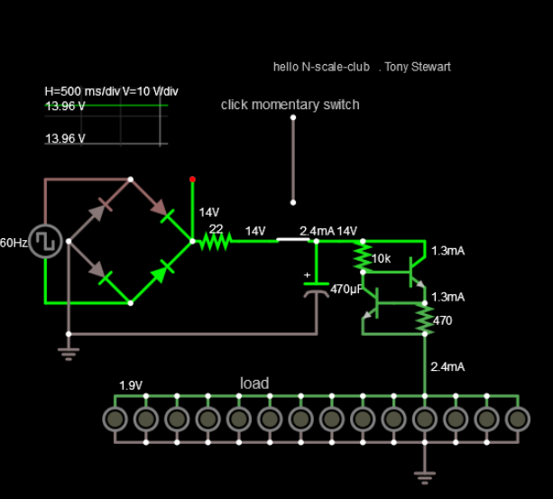
There are more efficient ways to do this. or there are simpler ways to get a long time constant.

enter image description here

The shared load current is 0.6Vbe/Re=470 = 1.2mA on the emitter.

Adjust to suit your requirement.

P.S.
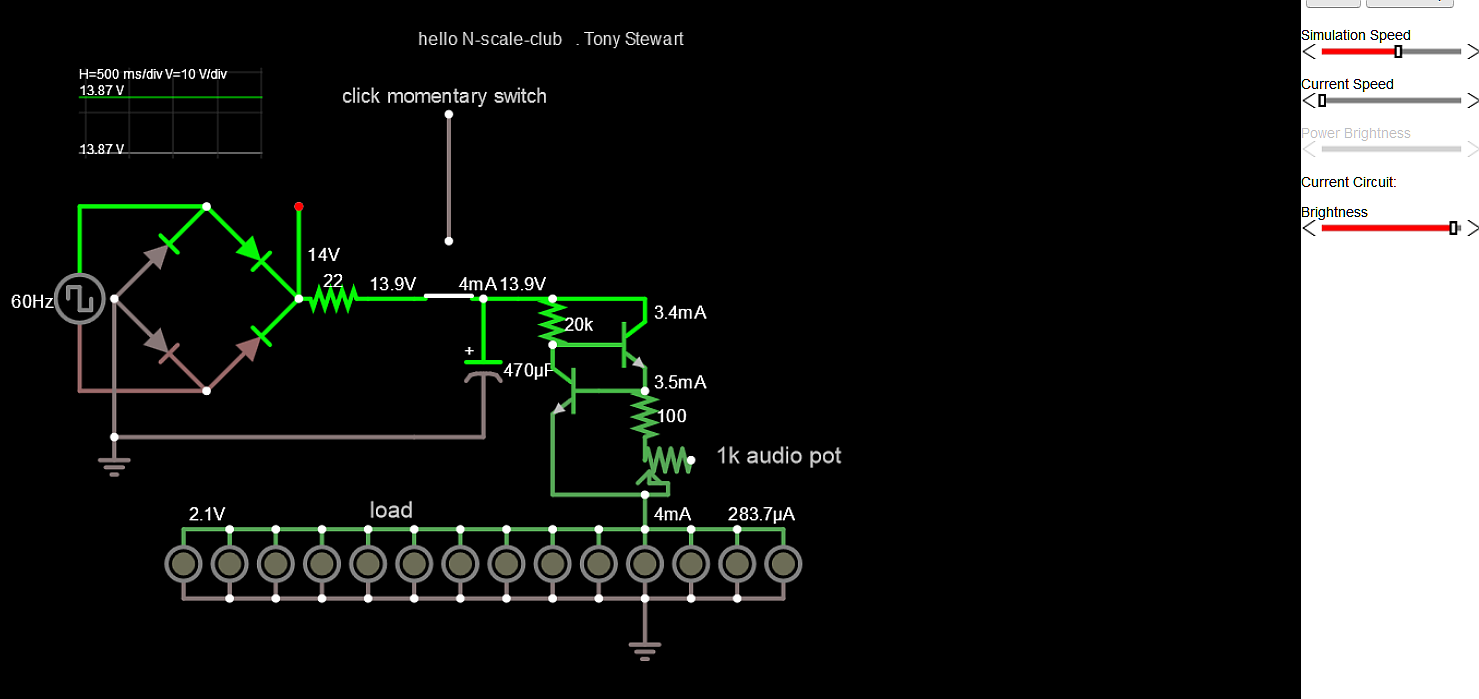
There is a risk after ? hundreds hours of use that the LED's go dark using only 100 uA. This is common effect and some MFG's warn against using below ~ 1~2mA currents. It just means the threshold for photoemission has risen above what was used due to an effect caused by such low currents. Pulsing to 10mA may or may not restore this dim light suitable for N scale realism.

The other approach is a 0.5% duty cycle pulse @ 200mA (shared) with 20kHz a Schmitt Inverter clock after this current limiter set for same 200mA or R3= approx. 3 Ohms could prevent this with the same low pass filter on supply and same average current.

To cut number of LED's Current must also be reduced with higher Re.

Rev B 12:10 PM enter image description here

\$\endgroup\$
9
  • \$\begingroup\$ Your current source is tried and true and simple +1 .Why not get some LEDs in series and maybe set up some more current . \$\endgroup\$
    – Autistic
    Commented Apr 20, 2019 at 5:46
  • \$\begingroup\$ @Autistic The diner cars are prewired and dim for N scale \$\endgroup\$
    – D.A.S.
    Commented Apr 20, 2019 at 11:46
  • \$\begingroup\$ +1 for mentioning the issues with low current on the LEDs. I learned something! \$\endgroup\$
    – Randy Nuss
    Commented Apr 20, 2019 at 14:06
  • \$\begingroup\$ @SunnyskyguyEE75 You cannot make any assumptions about pre-wiring and dim settings for any cars. This board is a project to add internal lighting to any n-scale wagon and many have no pre-wiring at all. LEDs are wired in parallel so that you can easily cut off ends of the board for length and only need to put as many LEDs on as you need to fit without having to put in jumpers or anything across any unused pads. \$\endgroup\$
    – chadbag
    Commented Apr 20, 2019 at 15:58
  • \$\begingroup\$ ok but then Current needs to be adjusted to share more current with more LEDs using a POT for Re and fixed R to limit current \$\endgroup\$
    – D.A.S.
    Commented Apr 20, 2019 at 16:00

Your Answer

By clicking “Post Your Answer”, you agree to our terms of service and acknowledge you have read our privacy policy.

Not the answer you're looking for? Browse other questions tagged or ask your own question.