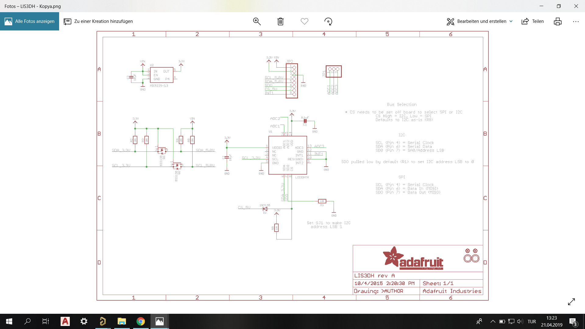
I need to design sensors card in altium for sensors connected I2C and SPI. When I searched modules on internet, while some used mosfet to handle high and low side others did not use mosfets. I could not understand clearly for which purpose they used mosfet. Could you help me, should I use mosfet connections for my card? To explain my question well, I added two diffirent photos for the same sensor type.
-
\$\begingroup\$ (a) "I added two [different] photos for the same sensor type." Actually you added only one schematic. Therefore the answers so far can only use the details from the one image that you supplied. If the other (missing) image is important to your question, then you need to edit the question, add the missing image, and explain why you think it is important. (b) "some used mosfet to handle high and low side" What do you mean by "high and low side"? I don't see any MOSFETs on the one image you added, being used in what I would call high/low side. Do you mean the I2C signals SDA and SCL? \$\endgroup\$– SamGibson ♦Commented Apr 22, 2019 at 13:15
3 Answers
The circuit shown is a common level shifting circuit for I2C. It is used because it can translate bi-directional open-drain signals as used in I2C.
I wouldn't recommend this circuit for use with SPI, because
- SPI doesn't require bi-directional translation.
- This circuit is slow (but it's difficult or at least tedious to predict how slow). That's okay for early generation I2C that runs at 100 or 400 kHz. But it's not adequate for SPI busses that might be expected to run at 1 - 10 MHz.
For SPI I'd recommend an off-the-shelf level translator IC to get predictable output levels and propagation delays.
Even for I2C if your application can accept a few $0.10's of extra cost I'd recommend paying for an off-the-shelf I2C translator IC to get predictable performance. Some of the available chips will also give a speed boost and/or allow you to power down one side of the bus without blocking communication on the other side.
They are using the MOSFETs as level shifters. If your devices do not all use the same voltage signalling levels, you may need to use them if your signals are bi-directional.
STM32 series microcontrollers can work directly with 5V peripherals just fine, without any MOSFET or other kind of level shifter.
Check the pinout table in the datasheet for your controller. Most pins are marked as FT, meaning Five-Volt Tolerant. These pins can safely take 5V input voltage when used as inputs (e.g. as the MISO line) or as open-drain outputs (SDA and SCL lines). Although they will output only 3.3 Volts when used as push-pull outputs, most 5V parts (check the datasheet of yours) would interpret a voltage above 2 Volts as a logical high level.
-
\$\begingroup\$ I won't use mosfet connection for SPI, if MISO connection supply 5V. But for accelerometer sensor MISO connection supply 3.3V. What should I do ? \$\endgroup\$– tgrCommented Apr 22, 2019 at 8:56
-
\$\begingroup\$ Check the datasheet of your accelerometer. The LIS3DH part in the above schematics does not work with 5V at all. \$\endgroup\$ Commented Apr 22, 2019 at 11:18
-
\$\begingroup\$ @MevlüdeTigre you can't use 5V to power sensor or uC. You need to learn the basics before start designing any electronic devices\ \$\endgroup\$ Commented Apr 22, 2019 at 19:57

