0
\$\begingroup\$

I'm working on a small project. I want to make an internet-connected dog food dispenser to attach to my dog's crate so I can dispatch a network command remotely to dispense it. I have a Raspberry Pi Zero WH with the Pi Cobbler attached to a breadboard and a small servo (Medium Plastic Gear Analog by OSEPP). The idea was to make something like this, where the servo would lift a small cardboard gate inserted into a cardboard tube to let the treats slide down.

I don't have a 4xAA battery holder, but have several 9V batteries and battery clips. I'm a software engineer, not electrical, so I mostly want to confirm a couple of things about the circuit design.

First is that I'm not sure how to calculate how much resistance I would need to use the servo (4.5 - 6V) with a 9V battery, if that's even possible. I know that if you just had a forward voltage drop of 2.4V for example, you would just use 6.6V as your voltage value in Ohm's law and the forward current of the servo as I. But how would I calculate this with a voltage range?

Second is that I'm not sure exactly how to insert the external battery source in the circuit. Do I just insert the positive lead in between the GPIO pin and the servo and the negative lead between the negative side of the servo and the GPIO GND?

Final question is that I just want to know... will the servo continually draw power from the batteries, even when inactive (pin isn't sending a signal to the servo). If so, is there a way I could set up the circuit to prevent this other than just adding a power switch?

I appreciate any help.

\$\endgroup\$
4
  • 1
    \$\begingroup\$ The problem with this plan is that the current drawn by the motor is not constant. Additionally, 9V batteries are some of the worst batteries on the market in terms of current capacity; they can barely provide any current at all, almost surely not enough to run a servo. \$\endgroup\$
    – Hearth
    Commented May 5, 2019 at 16:32
  • \$\begingroup\$ If you were going to use batteries, they should be 4 or 5 x AA. But your proposed wiring is all wrong. The two power supplies should have a common ground, you must not connect the servo power to a GPIO or you will kill your pi! And yes, the servo will draw power even when not moving - this really is not a practical idea. At best, if you found a regulator with an enable you could save the battery for actual movement. \$\endgroup\$ Commented May 5, 2019 at 17:10
  • \$\begingroup\$ @jsotola I hope that wasn't a serious question... I feed her in the morning and night. This is so I can give her a treat while at work. \$\endgroup\$ Commented May 5, 2019 at 22:23
  • \$\begingroup\$ @DarinBeaudreau, my apologies .... having dogs myself, i was just being concerned for the welfare of your dog \$\endgroup\$
    – jsotola
    Commented May 6, 2019 at 4:25

1 Answer 1

5
\$\begingroup\$
  1. Don't use a 9V battery to power your servos. 9V batteries have low capacity (won't last long.)

  2. Don't use a 9V battery to power your servos. 9V batteries cannot really deliver the current needed to drive one servo, let alone 3.

  3. Don't use a 9V battery to power your servos. You say your servos are rated for 4.6 to 6 V. 9V is too much.

  4. Don't use a 9V battery to power your servos. Lowering the voltage throws away half of the little energy they contain.

  5. You can't just lower voltage with a series resistor or a voltage divider. You have to use a regulator of some sort. A linear regulator is wasteful. A switching regulator is less wasteful (more efficient,) but a 9V battery is a poor choice in any case.


Obtain and use a battery holder for 4 AA batteries. That gives you 6V. Your servos will be fine with that.

Or, use a USB power supply that can deliver 1A. Your servos will be happy with 5V, and 1A should be enough current to operate all three servos at once.

I'd advise against using the 5V from the Pi. The servos could put enough noise on the power supply to cause the Pi to reset.

I suggest you work your way through a simple tutorial like this one before you get started writing your own software and building your gadget.

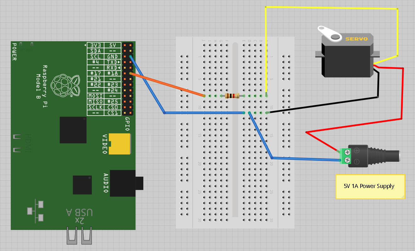
That tutorial shows you how to connect a servo to the Pi. Here's the wiring diagram it gives:

enter image description here

Note that the servo is powered separately from the Pi, and that the grounds are tied together.

The only real connection between the Pi and the servo is a control signal. The Pi doesn't touch the power to the servo.

The wiring diagram shows a resistor in the control line. It isn't required. You can leave it out if you don't have one.

Try out a tutorial, then look into pigpio.

Pigpio lets you use more than one servo on the Pi.

If you run into problems, ask a specific question about exactly whatever problem you encounter.

\$\endgroup\$
2
  • \$\begingroup\$ Thanks. This is helpful. But where did you get the "3 servos" part from? I'm only using one. Also, I didn't explain what I meant very well because I forgot that the servo has a control input as well as the positive and negative wires. I don't need any help with the GPIO area of this, as I've played around with the GPIO pins before, but from the technical sheet for the servo, it says it's 1 kg/cm at low voltage and 1.2 kg/cm at high. I don't really know how to tell if that's enough, but surely it should be enough to lift a small piece of cardboard, right? \$\endgroup\$ Commented May 5, 2019 at 22:30
  • \$\begingroup\$ Hmmm. The "three servos" bit seems to have crept in from another answer. Sorry. Yeah, 1kgcm ought to be enough to raise a cardboard flap. \$\endgroup\$
    – JRE
    Commented May 5, 2019 at 22:34

Your Answer

By clicking “Post Your Answer”, you agree to our terms of service and acknowledge you have read our privacy policy.

Not the answer you're looking for? Browse other questions tagged or ask your own question.