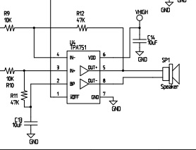
I need help to better understand differential amplifiers, when interfaced with an decoder IC. For the circuit below, which is from the reference design here:
It shows a mono differential amplifier (TPA751), driving a speaker on the same PCB. Not shown is the MP3 decoder IC (VS1003) driving the amplifier input. The amplifier has gain of -2Rf/Ri=2*47k/10k= 9.4. So the differential output is 9.4x the differential input.
As per the VS1003 datasheet, the output voltage from the CODEC (and input to the amplifier) is 1.7 Vpp (peak to peak) with a 1.2V DC offset. The outputs from CODEC and into the amplifier IN- and IN+ terminals are opposite of each other (ie. IN+=--IN-). I’m trying to understand how this circuit would work and would appreciate clarifications on the following points:
1.7 V peak to peak for the CODEC output means an amplitude of 0.85V. Therefore, with the 9.4 gain of the amplifier, the output to the speaker will be 0.85*9.4 = 8.0V peak to peak (OUT+ relative to OUT-). Is this correct?
If we measure OUT+ (pin 5 of the amplifier) with respect to ground and not to OUT- (pin 6 of the amplifier), the maximum amplitude will be 4V (ie. 4.7*0.8). So the signal will be from 0V to 4V. Is this correct?
Assuming the amplifier can produce a maximum voltage swing of VDD-1V, this means to avoid clipping, the power supply of the amplifier needs to be at least 5V. Is this correct?
My understanding is that speakers can’t handle DC offset. They must be driven by an AC signal. For our case above, based on the datasheet, there is no DC offset at the output. However, the output signal can be though of an AC signal with amplitude +/- 2V and a DC offset of 2V. Is this considered bad for the speaker? Or is this not a real DC offset?
Thanks! (This is my first ever post in this forum)

