2
\$\begingroup\$

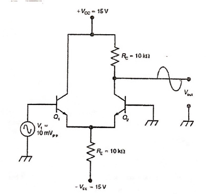
I've been trying to solve the circuit below for hours now but to no avail. I can't figure out what to do.

I've been given a single input, unbalanced output differential amplifier circuit to solve for the output voltage. This can be done if the input resistance and beta is given, but these two values are not given in the problem. Any values I've missed that I can use for input resistance and beta if they're not given in the problem?

enter image description here

\$\endgroup\$

2 Answers 2

8
\$\begingroup\$

Well, you could analyse the circuit to find the quiescent current in both BJTs. It's going to be about 0.75 mA in each. Can you see that?

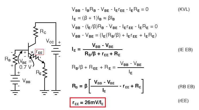
With a current of 0.75 mA, a BJT's internal emitter resistance (\$r_E\$) will be approximately 35 Ω. Here's a google example of that formula (red stuff by me): -
enter image description here

Image from here and, this degenerates aka causes negative feedback. I'm sure Mark Hughes won't mind me stealing his circuit and marking it up!

So, with 0.75 mA flowing, \$r_E\$ = 35 Ω. Given that there are two emitters joined (and ignoring the very small effects from \$R_E\$), the gain can be estimated as being \$R_C/70\$ = approximately 143.

Hence, for 10 mV p-p in, you would get 1.43 V p-p out.

This output voltage is small enough not to significantly affect the 26 mV/IE calculation done earlier.

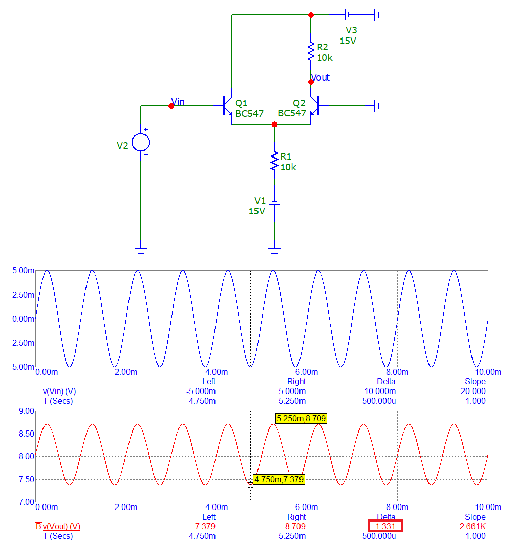
Sanity check using a simulator: -
enter image description here

The input signal (in blue) is 10 mV p-p and, the output signal (in red) is 1.331 volts p-p. That's a close result for a simple BJT circuit.

\$\endgroup\$
2
  • 1
    \$\begingroup\$ I have so much to absorb here. Thank you so much for the explanation Andy. Initially I assumed that Q1 and Q2 are equal hence which might've caused the confusion on my end. Electronics is so confusing xD \$\endgroup\$ Commented Sep 5, 2022 at 15:24
  • 2
    \$\begingroup\$ Q1 and Q2 can be assumed to be equal. Yes, with BJTs you can go quite deep. Maybe you should take the 2 minute tour to understand why folk give their time for free. \$\endgroup\$
    – Andy aka
    Commented Sep 5, 2022 at 15:26
3
\$\begingroup\$

When a "Common Base" has the base grounded, then the emitter resistor and \$(|Vee|-Vbe)/Re=Ie\$ controls the current directly.
Thus beta or hFE has no effect on the result.

When a "Common Emitter" also has a voltage source (0 ohms ) on the base, then the emitter voltage follows the Vbe voltage with some \$r_e\$ base-emitter bulk resistance.

A Differential BJT amp can be viewed as the two above connected together and is called the "long-tailed pair" It is voltage controlled current by the the base voltage to emitter changes. But as Vee the emitter negative voltage is much larger than Vbe it operates as a simple constant current sink. So if Q1 rises in current then Q2 must do the reduce in current and cause it's collector voltage to also rise.

This amplifier is not ideal as variations in bulk resistance in production and also temperature changes will affect the Vbe vs Ic gain of \$r_e=26mV/Ic\$ at 25'C only.

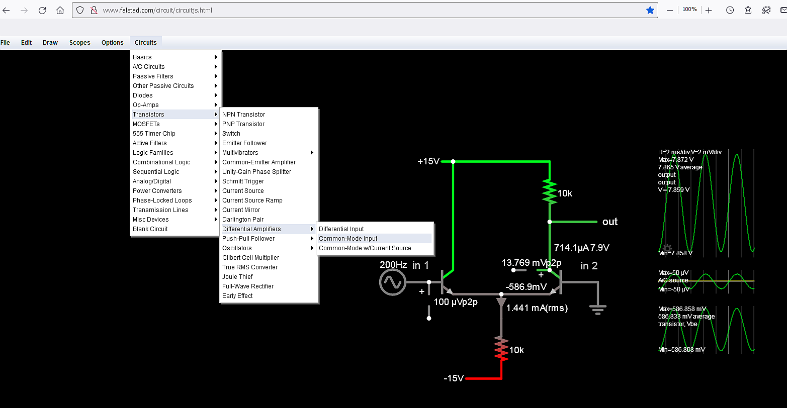
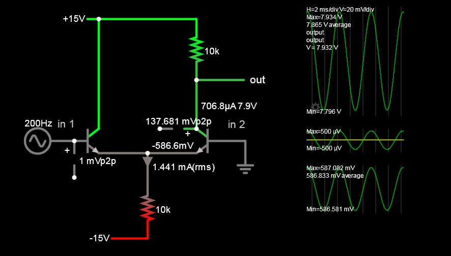
For giggles, I decided to mirror the simple 10k resistor long-tail diff. amp in Falstad's menu to compare with the gain vs a Spice program and then customize it.

enter image description here enter image description here His gain 133.1
My gain 137.681

Yet if I add 1 ohm to each emitters it reduces this gain to the same 133. Perhaps the gm is assumed at a slightly different room temperature. (?) So this is very close indeed and simple to use.

\$\endgroup\$

Your Answer

By clicking “Post Your Answer”, you agree to our terms of service and acknowledge you have read our privacy policy.

Not the answer you're looking for? Browse other questions tagged or ask your own question.