2
\$\begingroup\$

I have 16-bit Thunderbird12 Microcontroller, similar to the Freescale 68HC12.

I'm currently working on a project to monitor and control the level of water. Everything is working fine except for the input ports which have floating pins and they are randomly reading low and high. I did some research here and found that pull-up or pull-down resistors are the solution, but my set up is different.

There are 5 "sensors" that feed into the input ports. Each sensor is connected with 2 wires; one wire goes into the pin, and the other into VCC, then both are inserted into the container with both ends exposed. When the water level goes up, it touches both ends and completes the circuit and setting the input to 1.

The problem I have is that the input pins still read High even if the wires are not connected yet. What can I do do prevent this high impedance? I can't ground the wires or set them to 1, because the latter is supposed to happen only when the circuit is completed (when water touches them).

Any help would be appreciated, thank you!

\$\endgroup\$
9
  • 2
    \$\begingroup\$ Why not pull them up and have them go low when the water touches them? \$\endgroup\$
    – Ron Beyer
    Commented May 9, 2019 at 2:49
  • \$\begingroup\$ Thank you for the quick response!! Can you elaborate on the go low part? \$\endgroup\$
    – Dean
    Commented May 9, 2019 at 2:51
  • 1
    \$\begingroup\$ Why did you decide not to use a pull-up or pull-down resistor? \$\endgroup\$ Commented May 9, 2019 at 3:14
  • 2
    \$\begingroup\$ @Dean This is something you should just have fun experimenting with, I think. You can use a \$1\:\text{M}\Omega\$ resistor from ground to your "input wire." Leave the \$V_\text{CC}\$ wire hooked up to \$V_\text{CC}\$, as you already have it. So the only change is to add a resistor to ground from your I/O pin. (A very weak "pull-down.") This should be enough for your I/O to read "0" until the water reaches the wire-pair and hopefully will be enough of a connection to overwhelm the weak pull-down and give you a "1," instead. Adjust the resistor value, as needed. \$\endgroup\$
    – jonk
    Commented May 9, 2019 at 4:15
  • 1
    \$\begingroup\$ Nobody will be able to help with this unless you post the schematic, otherwise it is all just speculation. You are going to have some connectors between the sensor and the MCU, yeah? So you will always need pull resistors. HCS12 have them built-in on most ports, with some exceptions. \$\endgroup\$
    – Lundin
    Commented May 9, 2019 at 6:43

4 Answers 4

1
\$\begingroup\$

You still need a pull-up or pull-down resistor as appropriate. If the sensor connects between Vcc and the input pin, and if the sensor is open-circuit when off, then it would be a pull-down resistor. If the sensor connects between ground and the input pin, you need a pull-up resistor.

The resistor needs to be chosen so that it has a substantially higher resistance than the sensor.

\$\endgroup\$
2
  • \$\begingroup\$ Got it, thank you!! \$\endgroup\$
    – Dean
    Commented May 10, 2019 at 5:15
  • \$\begingroup\$ depending on what he uses weather or not he need external ones, because ic chips like a uln2003 has a "pulldown" built in. Which is nothing more than a bias stabilization for the input base circuit of the transistor inside the gate/buffer. \$\endgroup\$
    – drtechno
    Commented May 11, 2019 at 11:01
0
\$\begingroup\$

There are 5 "sensors" that feed into the input ports. Each sensor is connected with 2 wires; one wire goes into the pin, and the other into VCC, then both are inserted into the container with both ends exposed. When the water level goes up, it touches both ends and completes the circuit and setting the input to 1.

ok, there is some challenges here, first we have a simple sensor that completes an electrical circuit for a water level sensor. I see this part of the circuit is going to be weak for switching cleanly the micro-controller.

I would normally solve it by low power Schottkey inverters (74ls04) in series to clean up the signal going in. But since you need to trigger on a voltage, instead of completing a ground, then a nor gate (74ls02) circuit like the one below would work if you just use the "B" input for the sensor, nothing connected to "A" but the resistor to ground.

https://www.electronics-tutorials.ws/wp-content/uploads/2018/05/io-io81.gif

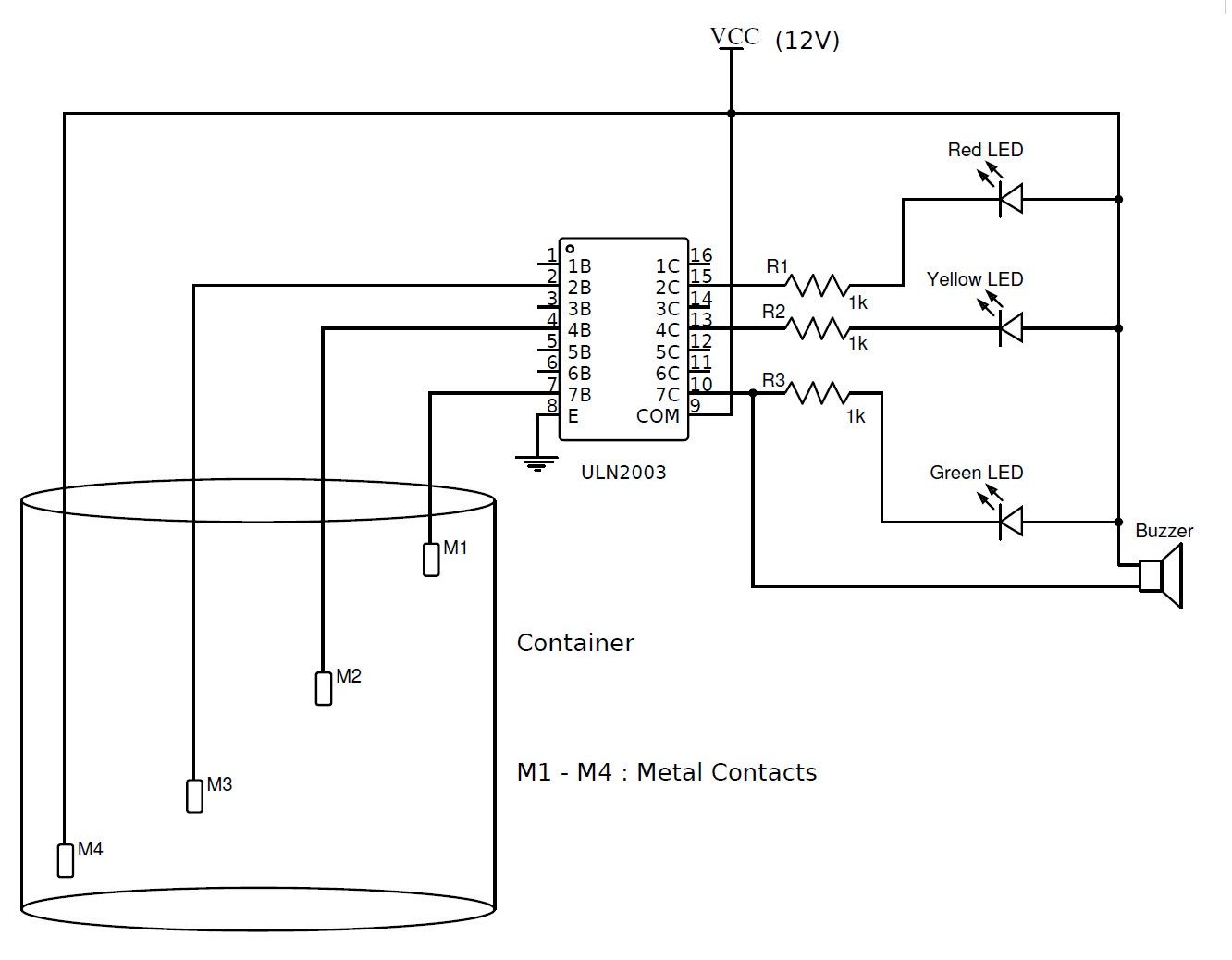
You could try high gain transistors, trasistor arrays (uln2003) or even a darlington comparator (that you can include a threshold adjustment) enter image description here

\$\endgroup\$
1
  • \$\begingroup\$ Very interesting, great info! I will definitely look into this, thank you for the neat schematics!! \$\endgroup\$
    – Dean
    Commented May 10, 2019 at 5:17
0
\$\begingroup\$

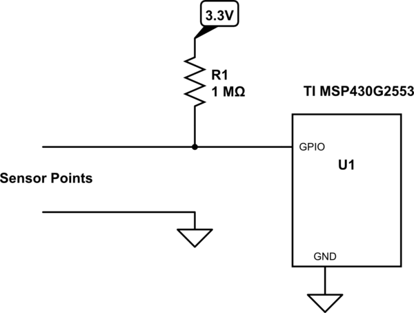
Since your GPIO pin has extremely high impedance, you need a pull-up or pull-down (as most people have said). I am working with a TI microcontroller right now, so I quickly wrote code for a quick test. I also didn't make any assumptions on the resistance of water, I used my tap water in a tiny cup for a test. It works with a 100k, so a 1M would provide good margin (for my water).

Your water may vary. The resistance of water is dependent on the impurities, really pure water has a very high resistance.

Finally, if your water container is really large and the water may already be grounded, you should use a pull-up resistor, not a pull-down.

schematic

simulate this circuit – Schematic created using CircuitLab

\$\endgroup\$
1
  • \$\begingroup\$ Thank you for taking the time to do all that! Yes, impedance is extremely high. My fingers would be 1 inch away from the ports and they would turn on and off erratically. I initially tested with tap water but the conduction was weak. I added salt, which seemed to do the trick. The container holds only one quart, just for testing reasons. I will try both and see which one works better. I tried the set up you illustrated in the schematics and it seems to be working fine. Thank you again! \$\endgroup\$
    – Dean
    Commented May 10, 2019 at 5:30
-3
\$\begingroup\$
  1. Check register port settings (check-> APB,GPIO PCLK...)
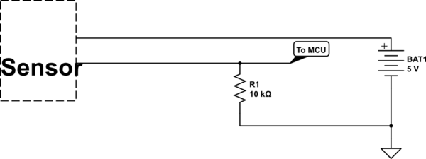
  2. You should use s pull-down about (4.7k ~ 10K) on Data Pin-->|GND--(10k)--SensorPin|
  3. Try output sensor state with a multimeter (without microcontroller)
  4. If your problems are not resolved, then post your schematic, sensor, microcontroller part number, source code

  5. Also, you could use an ADC

schematic

simulate this circuit – Schematic created using CircuitLab

\$\endgroup\$
3
  • 3
    \$\begingroup\$ Please improve the layout of your answer. Use the numbered list, etc. There is neither need for a big font size. \$\endgroup\$
    – Huisman
    Commented May 9, 2019 at 7:27
  • \$\begingroup\$ What is "APB" and "PCLK"? Sounds like you are speaking about some entirely different MCU than the one in the question. \$\endgroup\$
    – Lundin
    Commented May 9, 2019 at 7:39
  • \$\begingroup\$ "Send schematic. sensor... source code..." where? \$\endgroup\$ Commented May 9, 2019 at 7:41

Your Answer

By clicking “Post Your Answer”, you agree to our terms of service and acknowledge you have read our privacy policy.

Not the answer you're looking for? Browse other questions tagged or ask your own question.