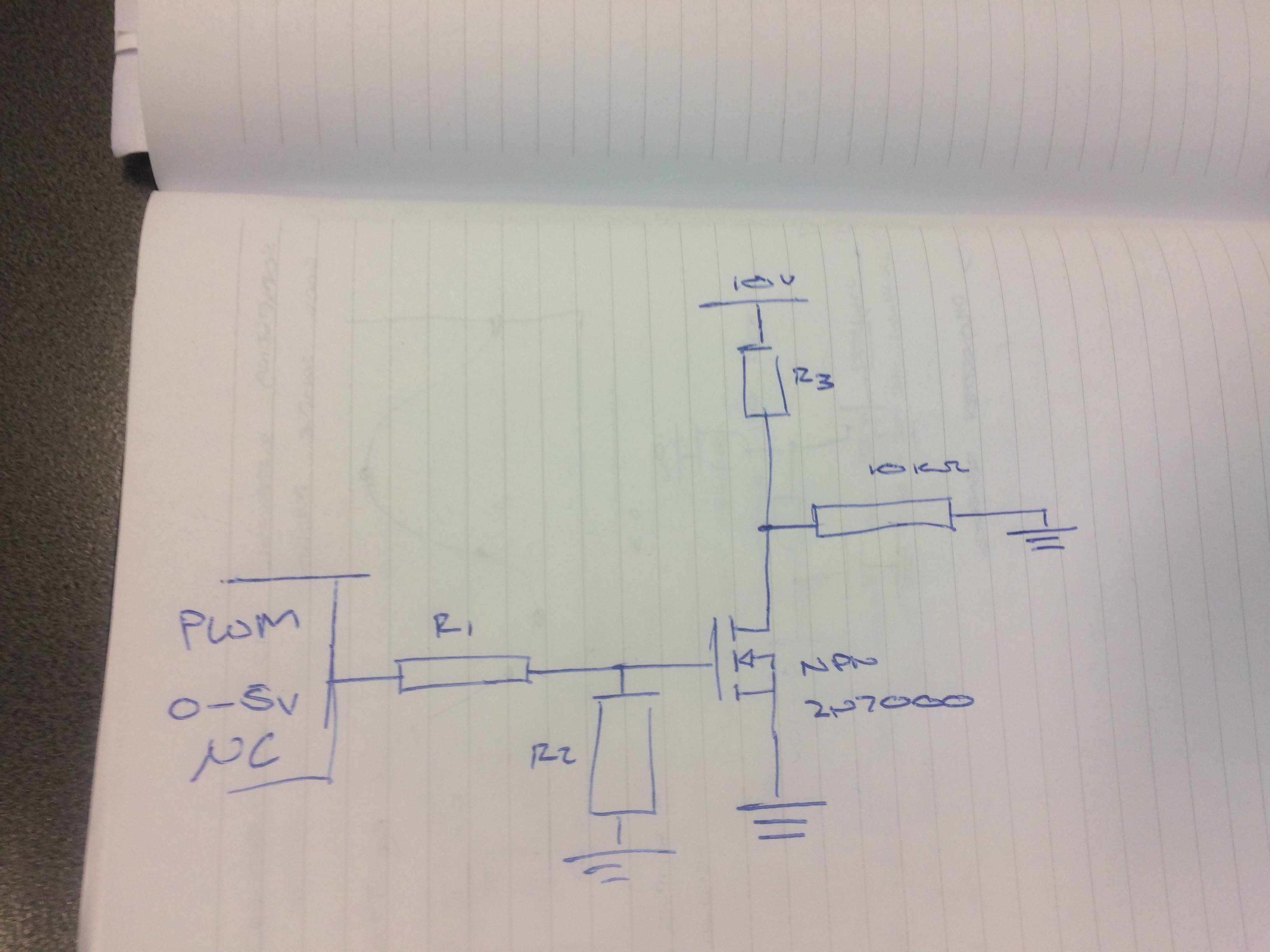
R3 is a pullup resistor. When the transistor is not conducting, R3 provides 10V to the load. When the transistor is conducting, R3 prevents the transistor from shorting 10V to ground. It can't be too large, because current to the load has to flow through it when the transistor is off, but it can't be too small, because current to ground will flow through it when the transistor is on (which will waste power and create heat.)
I am surprised the circuit is wired this way, instead of putting the load directly between the transistor and the 10v supply. That approach seems more normal to me. However, it reduces the voltage to the load by the voltage drop of the transistor. But it also provides a lot more current to the load than you would normally want to allow through R3.

