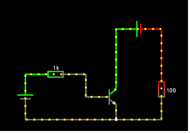
That looks like a BJT operating as a switch, to me. I can tell right away because you have \$100\:\Omega\$ in the collector circuit and \$1\:\text{k}\Omega\$ in the base circuit (about 10:1.) It's not a perfect way to tell, of course. But just "flying by" it's often good enough.
To design a BJT switch (assuming I already know if it needs to be high-side or low-side referenced), the first thing I need to know is the load current that will be switched. If it is within the capability of a small-signal BJT, that moves me in one direction. (If not, then I have to consider what kind of larger BJT I'll need and if I would prefer to use a MOSFET, instead.) In your case, the \$100\:\Omega\$ suggests some tens of milliamps to some low hundreds of milliamps so I can guess that a small signal BJT probably can probably handle it (as a first order guess.)
Let's say the supply voltage is \$15\:\text{V}\$ and the load is \$100\:\Omega\$. Then this suggests \$150\:\text{mA}\$ as a collector current.
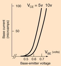
If you always keep in mind that the base-emitter voltage is a function of the collector current, such that \$V_\text{BE}\approx V_T\cdot\operatorname{ln}\left(\frac{I_\text{C}}{I_\text{SAT}}\right)\$ and that you might experience at most a 10:1 variation in \$I_\text{SAT}\$ with small-signal devices, you and easily work out the range you might experience with any particular device you grab from a box. In short, perhaps \$50-60\:\text{mV}\$ variation in \$V_\text{BE}\$ between devices given the same collector current.
So, a typical small-signal BJT will have a \$V_\text{BE}\$ of about \$700\:\text{mV}\pm 30\:\text{mV}\$ when the collector current is about \$4\:\text{mA}\$. In this example case, the current is \$\frac{150\:\text{mA}}{4\:\text{mA}}=37.5\times\$ as much. So this means \$V_T\cdot\operatorname{ln}\left(37.5\right)\approx 94\:\text{mV}\$ higher. So I'd guess that the base-emitter voltage (\$V_\text{BE}\$) will be, in rough terms, \$800\:\text{mV}\pm 30\:\text{mV}\$.
That's the figure I'd use when working out the value of the base resistor or estimating the voltage drop across it, if I already knew the value of it.
Most of the time, these variations don't account for enough variation to be worth the above trouble. When designing for a small-signal BJT as a switch, you usually over-do it anyway by using \$\beta=10\$. And for most small-signal BJTs, that's over-kill. So the \$100\:\text{mV}\$ error introduced by ignoring all of the above calculations usually isn't worth worrying about. (But if you only have very low voltage overheads to work with, then it may matter more.)


