4
\$\begingroup\$

I'm learning PIC C programming from Gooligum Enhanced C lessons. In lesson 14 CCP module there is example 4a which flashes LED every 500ms, see below: Using 16F1824 PIC

I can compile in MPLAB X and when I run it in simulation mode CCP2 which is shared with RC3 doesn't change state when TMR1 reaches CCPR2 value. I also loaded this in Proteus but LED doesn't flash also. Can anyone perhaps quickly compile this and see if it works? Or explain to me what is going on?

#include <xc.h>

#include <stdint.h>


/***** CONFIGURATION *****/ //  ext reset, internal oscillator (no clock out), 4xPLL off
#pragma config MCLRE = ON, FOSC = INTOSC, CLKOUTEN = OFF, PLLEN = OFF //  no watchdog timer, brownout resets enabled, low brownout voltage
#pragma config WDTE = OFF, BOREN = ON, BORV = LO //  no power-up timer, no failsafe clock monitor, two-speed start-up disabled
#pragma config PWRTE = OFF, FCMEN = OFF, IESO = OFF //  no code or data protect, no write protection
#pragma config CP = OFF, CPD = OFF, WRT = OFF //  stack resets on, high-voltage programming
#pragma config STVREN = ON, LVP = OFF


/***** MAIN PROGRAM *****/
void main()
{

/*** Initialisation ***/

// configure ports
TRISC = ~(1<<3);                // configure PORTC as all inputs
                                //   except RC3 (CCP2 output)

// configure oscillator
OSCCONbits.SCS1 = 1;            // select internal clock
OSCCONbits.IRCF = 0b0111;       // internal oscillator = 500 kHz 
                                //  -> 8 us / instruction cycle

// initialise Timer1
TMR1 = 0;                       // clear timer
T1CONbits.TMR1CS = 0b00;        // use instruction clock          
T1CONbits.T1CKPS = 0b00;        // no prescaler 
T1CONbits.TMR1ON = 1;           // enable timer
                                //  -> increment TMR1 every 8 us

// configure ECCP2 module
CCPR2 = 500000/8;               // initial compare time = 0.5 s /8 us/count
CCP2CONbits.CCP2M = 0b0010;     // compare mode, toggle CCP2 on match
                                // (CCP2 initially low)


/*** Main loop ***/  
for (;;)
{
    // Toggle CCP2 output every 0.5 sec

    // wait for CCP match
    PIR2bits.CCP2IF = 0;        // clear CCP2 interrupt flag       
    while (!PIR2bits.CCP2IF)    // wait for flag to go high
        ;

    // add 0.5 sec to last compare time        
    CCPR2 += 500000/8;          // add 0.5 sec / 8 us/count
} 
}
\$\endgroup\$

1 Answer 1

1
\$\begingroup\$

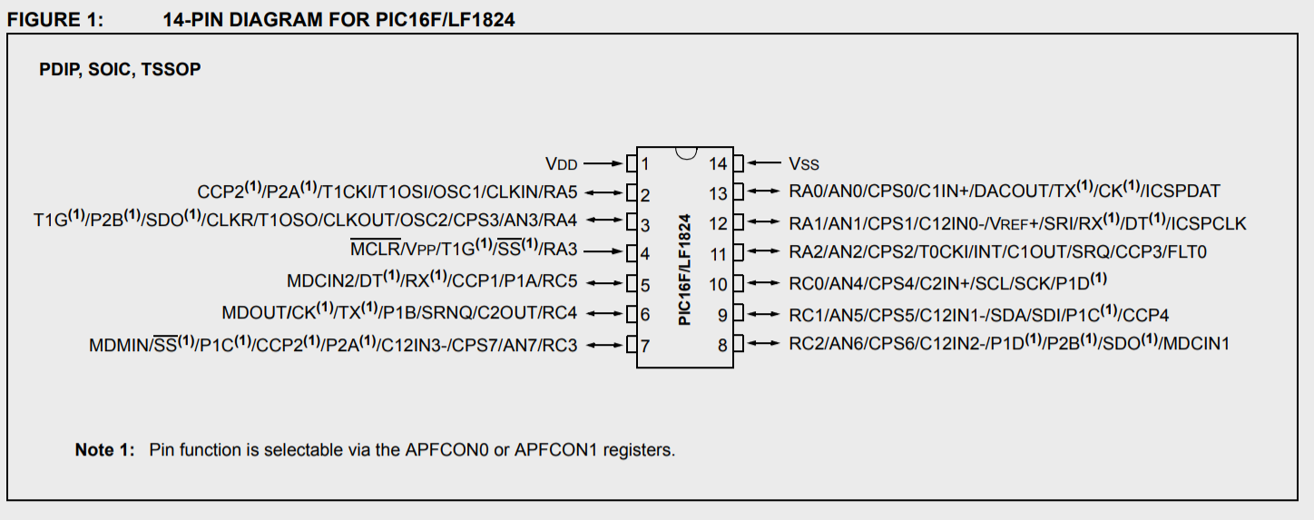
For the device you're using as you say the CCP2 pin is shared with other functions. As you can see in figure 1 on the datasheet:

enter image description here

You need to select the CCP2 function writing registers APFCON0 and APFCON1 with the right values in your configuration code, namely:

APFCON0 = 0b00100000;
APFCON1 = 0b00000100;

I simulated your code with MPLAB X IDE v5.20 adding these two lines and I can see pin RC3 under tab I/O pins toggling from 5V to 0V.

If you prefer you can instead use CCP1, just replaces all CCP2 instances in your code and set the correct value for TRISC (CCP1 is on Pin RC5).

I don't have a license for Proteus but I guess you can check that yourself and let us know if you manage to see your LED blinking.

EDIT: Since RC3 can also be made an analog input it is also necessary, as woj39 pointed out below, to explicitly set the pin as digital with:

ANSELCbits.ANSC3 = 0;
\$\endgroup\$
2
  • \$\begingroup\$ Marcos thanks for pointing me in the right direction APFCON statements didn't quite fix the problem but when you said I/O Pins tab I realized I need to start looking at this. At the beginning the MODE was showing as Ain and after the TRISC line it changed to Aout. I quickly realized that I need Dout Mode in order for the pin to work, so I added this line after TRISC line: ANSELCbits.ANSC3 = 0; // RC3 as digital I/O now it was showing Dout !! I'm using IDE v4.20 I wonder if that matters in this case at all? \$\endgroup\$
    – woj39
    Commented Jun 4, 2019 at 21:40
  • \$\begingroup\$ You're absolutely right. You have to set the pin as Dout too. If you do it you'll see activity on both tabs (I/O pins and Variables-PORTC). In my experience, the IDE version you use does matter; they have a lot of different chips, silicon revisions etc. and they keep improving and fixing bugs all the time. I have included your insight into my answer. \$\endgroup\$
    – Marcos G.
    Commented Jun 5, 2019 at 5:29

Your Answer

By clicking “Post Your Answer”, you agree to our terms of service and acknowledge you have read our privacy policy.

Not the answer you're looking for? Browse other questions tagged or ask your own question.