0
\$\begingroup\$

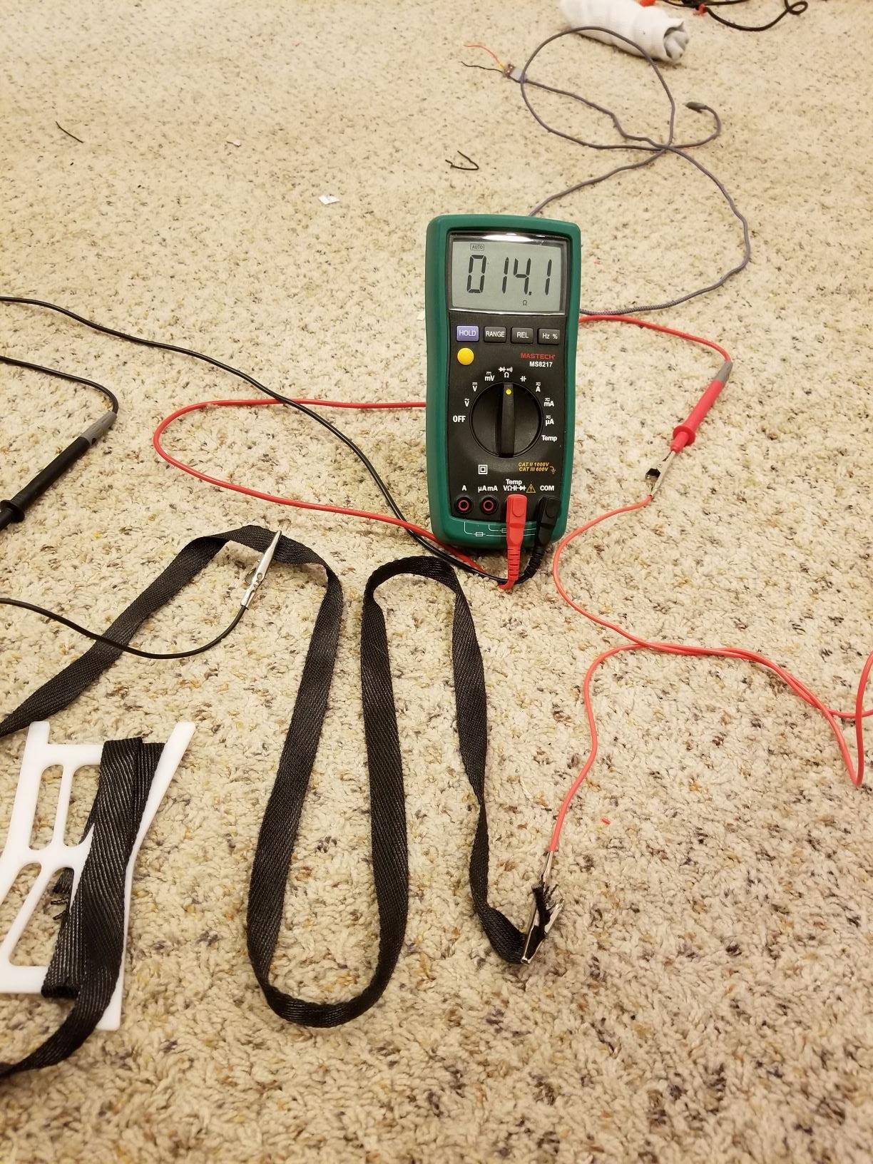
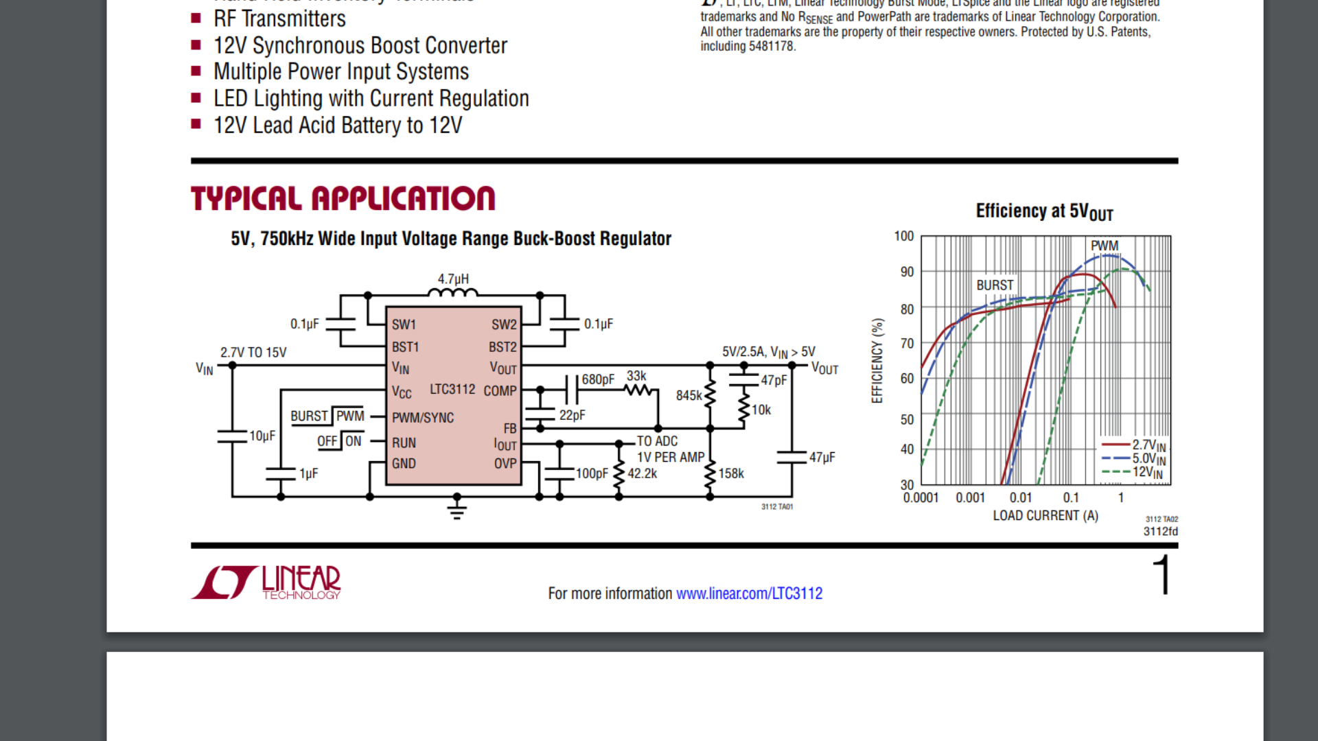
So for the past couple of days, I was testing out the LTC3112 Buck-Boost IC from Linear Tech. I'm using this for my heated glove project to step up/step down the voltage across the heating element. Using the typical application schematic for my test schematic with a 5V input (while changing the inductor from 4.7uH to 10uH), I tested the output voltage on an LED with a 1K resistor, and it was outputting 5V with appropriate current (of course). But when I switched to a piece of my conductive fabric (at 14 Ohms) as a load, the IC got damaged somehow and now is drawing 300mA - 400mA on the input side of my power supply even when there is no load attached and I am no longer getting a 5V output. Compared to a current draw of 0.027A when the IC was properly working.

enter image description here

I'm just trying to figure out what went wrong and why the IC failed me. The PWM/SYNC, Run, and Vin pin all received 5V. Unless my load somehow shorted itself (which I don't believe to be true), this IC should have been capable of outputting the appropriate current. I honestly don't know what the issue is at this point.

https://www.analog.com/media/en/technical-documentation/data-sheets/3112fd.pdf

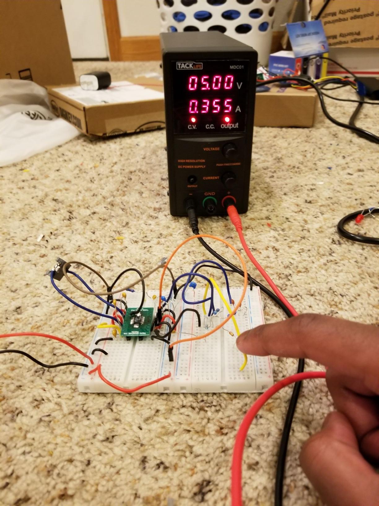
The yellow wire I'm point to/touching is Vout with no load connected. enter image description here enter image description here
\$\endgroup\$
8
  • \$\begingroup\$ All wires are also inductive depending on L/W ratio and I estimate since ~50 Ω/ m and 0.5uH /m your fabric is also 160 nH which is pretty small but at 1.5MHz would add 1.5 Ohm reactance, which should be OK. So I suspect handling and layout issues neglecting the datasheet guidelines which may affect the stability, loop response and over-current shutdown. Did it ever get hot? \$\endgroup\$
    – D.A.S.
    Commented Jul 28, 2019 at 4:23
  • \$\begingroup\$ The fabric? No. But it wouldn't have gotten noticably hot at 0.4A anyways. At around 0.75A is when it starts to feel warm. \$\endgroup\$
    – Jay
    Commented Jul 28, 2019 at 6:07
  • \$\begingroup\$ If you suspect the IC failed, when did you notice it getting warm? Can you list all the voltage readings or scope results? of each important pin in your Q? \$\endgroup\$
    – D.A.S.
    Commented Jul 28, 2019 at 12:20
  • \$\begingroup\$ Were any connections intermittent or any clues during this change?? \$\endgroup\$
    – D.A.S.
    Commented Jul 28, 2019 at 12:25
  • \$\begingroup\$ I wasn't measuring the temperature of the IC, so I don't know if/how warm it got. I know the component failed since the the current draw on my power supply increased from 2-10mA (I don't remember the actual number) to 400mA. And the current draw was constant, even with no load attached. I don't have any oscilloscope readings since I can't afford one at the moment. \$\endgroup\$
    – Jay
    Commented Jul 28, 2019 at 20:28

2 Answers 2

2
\$\begingroup\$

Assuming that you went through all of the proper component selecton (for a DC to DC converter, all the components must be selected by guidelines listed in the datasheet) (you cant use any inductor or capacitor you want)

With a setup like that, the IC probably is suffering from an electrostatic discharge. Carpet is no place to troubleshoot circuits. The IC can support 1A at 5V so it's most likely not the heater. Replace the IC, find a bench and possibly an ESD mat with a strap. Then slowly 'ramp' up the load with lower and lower value resistors.

Another problem that you may be facing is the poor parasitics of the breadboard. The ESR of the inductor will be much higher with the contact resistance of the breadboard. With many DC to DC designs, the making the traces that are 10's of mills can create problems with a design (milliohms make a difference).

The resistance on the pins plus the contact resistance is probably causing issues also. If you get this up and running again check the voltage bounce on the ground pin of the regulator before going to full current with an oscilloscope.

Also the loop will not be properly compensated as there is roughly 20pF of capacitance between rows, this could also cause problems with the compensation which could lead to instability in the feedback loop of the buck converter.

Don't use a breadboard with DC to DC's, use perfboard and soldering or wirewrapping. Use the PCB layout guidelines (even when soldering)

\$\endgroup\$
1
\$\begingroup\$

This converter switching frequency can be as high as 1.5 MHz. This means that external components selection and a good PCB layout are critical for its stability and for proper functioning, including reliability (survivability) under load.

You have overlooked this fact and used a protoboard to build it. External components selection may have been compromised too. Pages 14 to 17 of the datasheet guide you through the process of selecting critical components like the inductor and input and output capacitors. The manufacturer goes as far as providing specific part numbers, whereas you seem to have selected your parts from a generic breadboarding component kit. Note also that the manufacturer recommends a specific PCB layout in order to minimise parasitics, etc. but your protoboard implementation can't control that.

It could be that the circuit was working marginally without load, and then you ran into catastrophic stability problems under load.

\$\endgroup\$

Your Answer

By clicking “Post Your Answer”, you agree to our terms of service and acknowledge you have read our privacy policy.

Not the answer you're looking for? Browse other questions tagged or ask your own question.