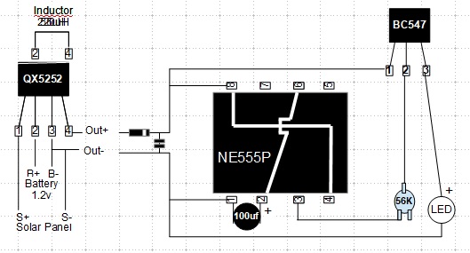
I have a standard NE555P fader circuit powered via a 1.2 V battery boosted by a QX5252 with 220 µH axial inductor (which according to the datasheet should be giving an output of 3.5 DCV @ 15 mA to the NE555P). The net max. output from the 555 circuit is about 2.5 VDC after an NPN boost, which is OK for my red, yellow, and green LEDs but only dimly lights up blue LEDs.
I wish to boost final power output from the NE555P circuit of 2.5 DCV to 3.0 DCV (or thereabouts) at around 10 to 15 mA.
I'm unsure how to approach the increment problem at such low voltages.
Previously, I didn't provide a schematic, but did provide a description; here is a schematic:
Power supply:
Typical solar garden light circuit. 1.2V 2100 mAh battery boosted by QX5252 with 220 μH axial inductor between pins 2 and 4.
According to the datasheet this should result in an output of 3.5 VDC @ 15 mA. QX5252 Datasheet QX5252 Datasheet
I've modified the output of pin 4 with a Shockley diode and a small 603 capacitor, the same mod I created on instinct to get RGB functioning in another project, but maybe there is a better way (?). Anyway, the NE555P doesn't trigger without this mod.
NB: Yes, I know the 555 datasheet recommends 5 VDC in. However, other people's research and my own experimentation proves the 555 can work fine down to 1 V (which is all well and good when not playing with LEDs, which may need between 2 to 3 V at respectable mA levels to get desirable brightness).
Fader:
Standard 555 fader circuit. Pin 3 (output) via 50 kΩ pot plus pins 2 and 6 to BC547 base, pins 4 and 8 to BC547 collector. A 100 µF cap between pins 1 and 2. A LED between BC547 emitter and pin 1 (optional mod for red & yellow LED = appropriate resistor between BC547 emitter and + lead of LED). Power + to pin 8, - to pin 1.
Options:
Playing with pin 5 on the 555 seems to be a possible option to increase the DCV output of pin 3, but I could not find any examples on the internet, just a throw away comment that pin 5 is rarely used in circuits but can be used to modify the 2/3 output of pin 3. Somehow I don't think that is going to solve my problem. Instinct is telling me that a simple mod around the BC547 might be a better option (?).
Any pointers to websites or preferably the provision of schematics to advance my project would be most appreciated.
About me:
I'm just a retired old fart with limited resources who last played with solid state electronics when SCRs had just become available but didn't get the opportunity to play with them (late 1960s?). I have a fair amount of catching up to do in understanding ICs etc. Apart from the basic VRI formulas I'm at a bit of a loss.
My current aim is to make low powered & solar powered toys and novelties for my grandkids (and me!), and share whatever I create on the internet (once I figure out how to edit videos and have something worth sharing).

