7
\$\begingroup\$

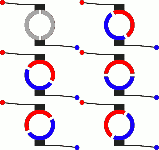
I understand the field magnets attracting/repelling the armature/coil so that it turns one half-turn and then, because the commutator is turned, its contact with the brushes has switched sides, and the current goes in the opposite direction, reversing the electromagnetic polarity. Then, because the polarity is swapped, it attracts/repels to complete the second half-turn. The thing is, isn't it a bit of a gamble that it will turn in the same direction? Couldn't the it just be pulled/pushed back, more or less undoing the half-turn?

I'm also a bit confused how the rotation doesn't just stop once the commutator is oriented so that the brushes are contacting both sides of the commutator. In other words, there's a brief period just as the commutator switches the current directions where each both the brushes are in contact with both sides of the commutator where the current is neutralized. Shouldn't this stop the motor?
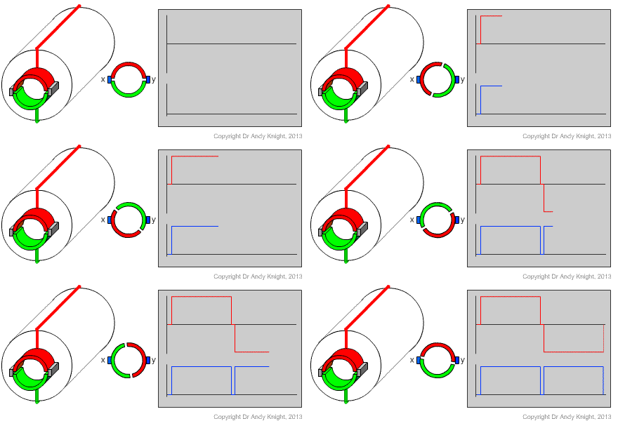
current of commutator

For reference, I'm just talking about a simple DC motor.

\$\endgroup\$
6
  • 2
    \$\begingroup\$ I think that’s a simplified diagram, real DC motor commutators have at least 3 contacts if I remember correctly. AFk(phone) so cant easily find a better image... \$\endgroup\$
    – MarkU
    Commented Aug 13, 2019 at 23:39
  • 1
    \$\begingroup\$ DC motors are really super cheap. Get some (or get some toys with them from a second hand shop) take them apart, and look inside. \$\endgroup\$
    – TimWescott
    Commented Aug 14, 2019 at 0:23
  • 1
    \$\begingroup\$ This has somewhat been covered in some of the other answers and comments but I would like to add that I have in fact built such a motor and it does in fact work. Once the motor is up to speed, the inertia of the rotating part will keep it turning in the same direction instead of reversing direction. If I remember correctly, this design of motor can however be started in either direction (e.g. if you stop the shaft with your fingers and then flick it back the other way). \$\endgroup\$ Commented Aug 14, 2019 at 16:17
  • 1
    \$\begingroup\$ Regarding the shorting of the contacts during the crossover, this did also happen with my motor however it doesn't stop the motor as again the inertia will carry it across. However it will cause arcing between the brushes and the contacts and create a sudden high-current spike on the power supply, both of which are a bad idea. In my case, adjusting the size of the contact area between the brushes and the contacts so that it was smaller than the gap between the two contacts avoided this. \$\endgroup\$ Commented Aug 14, 2019 at 16:17
  • 1
    \$\begingroup\$ So the short answer is that this simple design will in fact work and will in fact turn in either direction but once it's turning the inertia of the rotating part will keep it going in the same direction even under some load. However as others have pointed out a real-world DC motor will almost certainly use an improved (but more complex) design that ensures that the motor will always turn in the same direction and avoid arcing, and I have also disassembled real DC motors and seen this for myself. \$\endgroup\$ Commented Aug 14, 2019 at 16:21

3 Answers 3

12
\$\begingroup\$

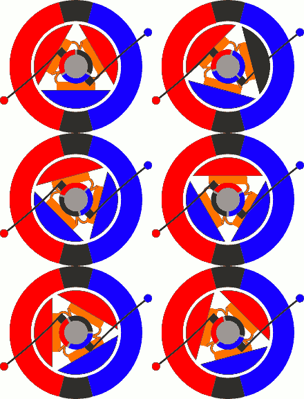
A normal DC motor has 3 poles instead of just 2. This solves a couple of problems:

  • the commutator doesn’t short out as it crosses from one pole to the other.

  • the energized poles are always phased with the field magnets such that they never get in a place where they’re ‘stuck’.

This Quora link has an animated illustration that shows the idea: https://www.quora.com/Why-do-most-brushed-DC-motors-have-3-armatures-and-not-2

And to save you the trouble of following the link, here are the ani-GIFs:

enter image description here enter image description here

Wow, party like it's Internet 1999 again!

\$\endgroup\$
3
  • 2
    \$\begingroup\$ If that's the case, why do diagrams even bother with the two pole design if it can't even work? I understand minimalism for simplicity, but generally, minimalism reduces things to a point when they are still functional \$\endgroup\$
    – Nicholas
    Commented Aug 14, 2019 at 0:27
  • 2
    \$\begingroup\$ Probably because it's simpler to understand, at least at the beginning, But, yes, it's unworkable as real motor. I remember making paperclip motors like that as a kid. \$\endgroup\$ Commented Aug 14, 2019 at 0:29
  • 3
    \$\begingroup\$ Having said that, looking back on it a second time, I'm not sure 'unworkable' is the right word; 'impractical' might be better. I suppose it can function, it's just really unreliable because it has to be going faster than a minimum speed and must not stop in the wrong position. \$\endgroup\$
    – Nicholas
    Commented Aug 14, 2019 at 0:52
5
\$\begingroup\$

Inertia carries it through. I also think the brushes are arranged so only one slip ring can touch the brush at a time, otherwise you would get a short-circuit twice per rotation. Despite the image showing both slip rings touching the brush, the waveforms say different.

\$\endgroup\$
6
  • 1
    \$\begingroup\$ I can see that at certain speeds, depending on how heavy the motor is, but wouldn't that mean that the motor can't run slowly? If the motor is idling along, It wouldn't have a ton of inertia. Also, I'm kind of confused about the brush thing. First off, if the brushes can only touch one slip ring, then the gap between the split rings would have to be wider than the brush. Even if it wouldn't cause a short circuit, it'd still stop the current. Secondly, so far as I can tell, the waveforms are showing the same as the image. When both slip rings touch the brushes, the red wave drops to zero. \$\endgroup\$
    – Nicholas
    Commented Aug 13, 2019 at 23:37
  • \$\begingroup\$ @Nicholas, Many motors also have a preferred "off" orientation, where the brushes will be at certain predictable locations. When it starts again, it goes in its preferred direction. If a motor is running at very low power, it will find itself resting in that "off" position again and again. And you're right, since the gap in the rings is wider than the brushes, the current does indeed stop, by design. If the motor stops in that position, it may be difficult to get it going again, but thanks to its "off" position, most motors will quickly find themselves in a usable state again. \$\endgroup\$
    – Ghedipunk
    Commented Aug 13, 2019 at 23:46
  • 2
    \$\begingroup\$ @Nicholas, also most consumer electric motors don't just have two windings, two fixed magnets (stators), and two slip rings, as shown in the diagram. A basic DC motor will have 3 windings with 2 stators, with the slip rings arranged in a way that lets one of the windings be disabled while the other two are driving the shaft. \$\endgroup\$
    – Ghedipunk
    Commented Aug 13, 2019 at 23:55
  • \$\begingroup\$ @Nicholas The blue wave also drops to zero which means it is definitively not connected. You can get zero volts between sliprings if they are both connected or disconnected and floating. That dead time doesnt matter. Even in electronically commutated motors you have a dead time so short circuits dont occur. This is just the mechanical equivalent. It doesnt stop the inertia from doing its job. \$\endgroup\$
    – DKNguyen
    Commented Aug 14, 2019 at 0:36
  • \$\begingroup\$ @DKNguyen But the inertia required to turn it far enough means there is a point where the engine would be running too slow? It probably wouldn't continue to work if an average sized motor is turning about 0.5mm per second. This makes be a bit confused as to how giant heavy motors work. They would continue to have a lot of inertia once they are going, but starting them up must be incredibly difficult. \$\endgroup\$
    – Nicholas
    Commented Aug 14, 2019 at 0:38
4
\$\begingroup\$

The motors like the one in your picture bear a lot of resemblance with primitive combustion engines. They require a push to start, and will keep rotating in the direction in which they have been pushed. They can only run smoothly if the rotor has sufficient inertia, if not, a flywheel must be added to increase it. And finally, they cannot run reliably at arbitrarily low RPM.

Such motors are good for illustrative purposes, but are currently never used in practice.

\$\endgroup\$

Your Answer

By clicking “Post Your Answer”, you agree to our terms of service and acknowledge you have read our privacy policy.

Not the answer you're looking for? Browse other questions tagged or ask your own question.