1
\$\begingroup\$

I'm having those fancy ESP boards that come with a battery input pins/holders that can be connected to a battery to make them portable. They also have a dedicated USB port for charging/sketch uploads.

However, these ESP boards do not protect the cell against short-circuit or come with over-charge/low voltage protections. My intention is to use the cheap "18650 charging modules" that come with TP4056 chip and battery protection ICs, such as this one.

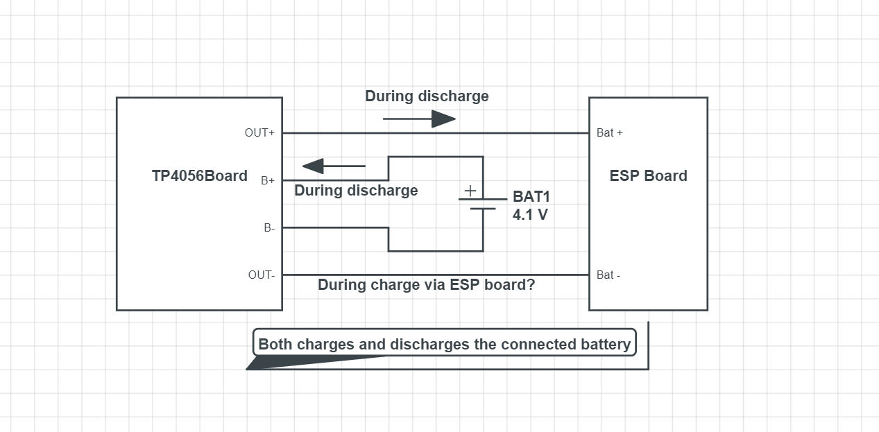
After wiring up, the output from the TP4056 module goes to the ESP board. There's just a problem. It'll work fine when the setup is being discharged, but how does it get charged when the ESP board gets connected via its USB? It just sends ~4.2V to the battery connectors and since this is already connected to the output of these modules, I'm worried if there might be any damage to the to either of these boards. I could charge them separately but during sketch uploads, the battery terminals are going to be fed with the charging voltage anyhow.

I'm wondering if it's somehow already safe against a reverse current, or should I add something to make this work.

Edit: Here's roughly what I mean:

A rough schematic of what I want to make

\$\endgroup\$
4
  • \$\begingroup\$ I have a setup just lik yours. Lolin32 with a TP4056. Never have any problems though. You can always use OTA. \$\endgroup\$ Commented Aug 20, 2019 at 18:20
  • \$\begingroup\$ Can you please draw the setup? It will be easy to comprehend \$\endgroup\$
    – User323693
    Commented Aug 21, 2019 at 6:03
  • \$\begingroup\$ @Umar Here's the simplified schematic. Here's the MSPaint version. Thanks! \$\endgroup\$
    – 1NF1N17Y
    Commented Aug 21, 2019 at 16:27
  • \$\begingroup\$ @MarcoTulioSouza Does it actually charge the battery to safe limits, when powering with its output terminals? \$\endgroup\$
    – 1NF1N17Y
    Commented Aug 21, 2019 at 16:28

1 Answer 1

0
\$\begingroup\$

No blocking diode is required due to the internal PMOSFET architecture and have prevent to negative Charge Current Circuit.

TP4056 modules do not take input current or reverse current form the circuit it is powering.

You can use one PFET as a diode to block the current from the BAT+ module pin of the ESP to the OUT+ pin of the TP4056 module. This is extra but you will be definitely sure that you are not then trying to charge the battery via USB cable used for sketch upload. Alternatively, if you can share the schematics of ESP module, we can find a way to isolate it.

\$\endgroup\$

Your Answer

By clicking “Post Your Answer”, you agree to our terms of service and acknowledge you have read our privacy policy.

Not the answer you're looking for? Browse other questions tagged or ask your own question.