2
\$\begingroup\$

My 2000 honda civic has an incandescent dome light that has PWM controlled "dimming". It takes a period of about 6 or 7 seconds when the domelight goes from full bright (not pulsed) to a pulsed duty cycle so the bulb dims slowly. I took some measurements with my scope when it is doing this.

The frequency is a constant 63.7hz. When it goes into this PWM controlled dimming it starts at about 60% on-time duty cycle. It reduces the "on time" and ends up going from this 60% to about 5% over a period of about 6 or 7 seconds.

The problem with this 63.7hz, is that it is not a super fast pulsing and I can see it with my naked eyes when I connect an LED strip to it. The goal of this project is to prevent the visible flicker when it dims with an LED circuit instead of a bulb.

I drew up an LED circuit with 27 LEDs- (9 parallel strings of 3 LED in series- each string has its own current limiting resistor) it will draw about 470ma total when connected to 14v. It has an effective resistance of 20 ohm.

The factory bulb that is in there draws about 600ma when it heats up (I measured on the bench). This means at steady state when everything is working the LEDs will draw about 130ma LESS than the original incandescent stuff.

I want to use a capacitor so that it will smooth out this dimming while it is PWM. The problem I am having is that I can't find a way to be sure on what capacitor value to buy. I want to get the smallest capacitor I can, and still do the job. Since my circuit draws 130ma less than factory, I can use a resistor to slow the charging of the capacitor (14v divided by 130ma is about 100 ohms in front of the capacitor- this way I will not ever draw more than the original 600ma that it draws from the factory with the bulb fully warmed up- this should protect the driver that controls the circuit in the car)

I was also thinking i should "diode isolate" the charging and discharging of the capacitor so that the discharging does not have to go through the charging resistor. The LEDs and the resistors on the output side should take care of this right? I assume it will see this as a 20 ohm load.
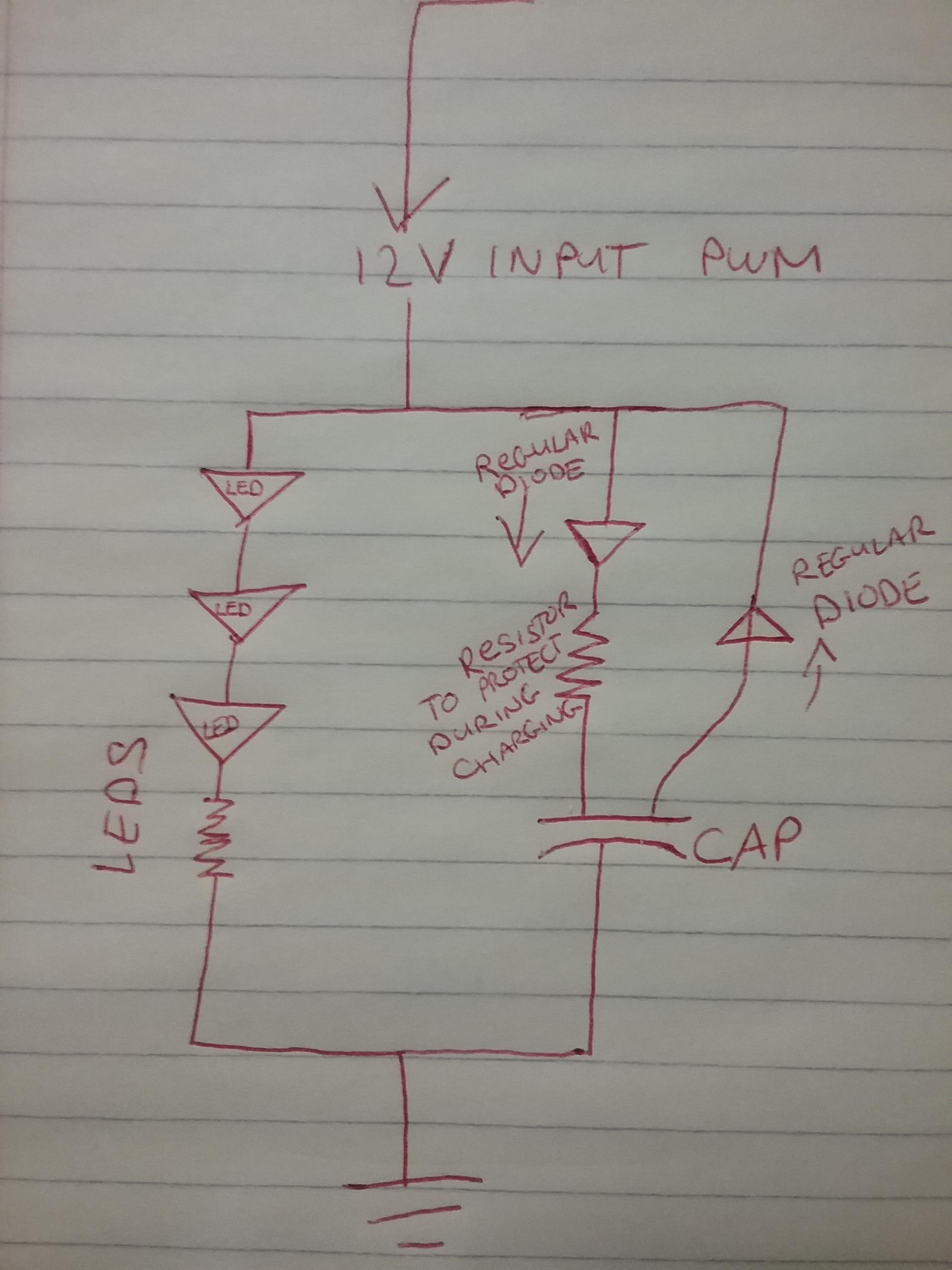
enter image description here Here is a video of the entire system working when I was playing around with it first understanding how it works better. (sorry this video is sideways!) https://drive.google.com/open?id=149BNC7PA8Fv81TNguBFgFEfnkXbPAcyn

I do not mind a delay of about .5 seconds while the capacitor charges. I just don't want to draw too much current over the driver in the car. I do not mind if it changes the 'fade duration', I just want to hide the visible 'flickering' that I see because the frequency is too low.

\$\endgroup\$
2
  • 3
    \$\begingroup\$ Just put the capacitor in parallel with the LEDs themselves (assuming you have access to that node). I can't tell you the value, though -- I'd arrive at it by experimentation. \$\endgroup\$
    – TimWescott
    Commented Sep 5, 2019 at 14:56
  • 2
    \$\begingroup\$ Isn't that what I have drawn? The capacitor will need some sort of resistor to slow down the charge though right? Otherwise it will draw too much current when it begins to charge from empty? \$\endgroup\$
    – djturbojp7
    Commented Sep 5, 2019 at 15:19

1 Answer 1

0
\$\begingroup\$

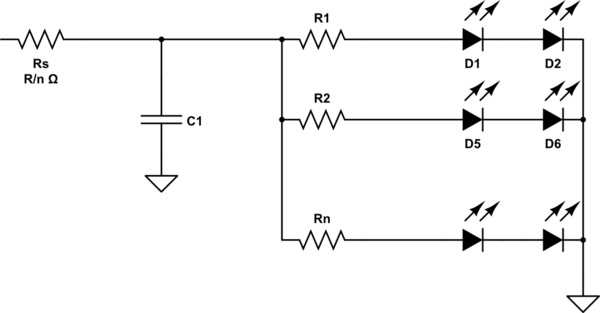
Maybe use fewer series LEDs (so that it's less sensitive to voltage) and just use an RC (split the series resistor). 470mA seems a bit high if you are using decent LEDs- usually the ratio between incandescent bulbs and LED is more in the 6:1 range, and low voltage tungsten bulbs tend to be less efficient. But maybe you want more light..

So if you use 2 LEDs in series and 13 pairs, each with 15mA, that's 200mA total. You need to drop about 8V with the motor running and maybe 5V with the motor off, so let's calculate for 7V, 3.5V across the string resistors, so about 220 ohms each and 3.5V across the series resistor so about 16 ohms. The RC thus sees about 8 ohms. If the RC is to be in the 100ms range you would need around 12,000uF, which isn't crazy big. You can recalculate for the larger capacitor required if you really want to go up to 470mA. But something in that range would likely work. The peak current (from the MOSFET or BJT driver in your car) would be around 14V/16 ohms or 875mA which is probably acceptable since incandescent bulbs draw several times steady state current when cold.

schematic

simulate this circuit – Schematic created using CircuitLab

Note: The driver is probably an open-drain or open-collector high side driver, so series diodes are not required and will add voltage drop. We're kind of guessing on the required time constant too. This is really the sort of thing where you are probably best to cut and try.

\$\endgroup\$
3
  • \$\begingroup\$ This is a ground side switched controlled circuit. I took the dome light off and measured at the connector- it always has battery voltage, but the computer pulses (or gives) it a ground. As far as the brightness goes, I have these leds that are 60ma each nominal draw, I wanted to give them about 51ma since it gives it some headroom. I like things crazy bright. \$\endgroup\$
    – djturbojp7
    Commented Sep 5, 2019 at 16:53
  • \$\begingroup\$ @djturbojp7 Okay, same idea then, just lower resistances (and low-side switched, obviously). You would need more capacitance, maybe 25,000 or 30,000uF 16V. Eg. Nichicon UVZ1C333MRD 33,000uF/16V. 25mm diam x 52 high, a bit big. You might need to add a bleeder resistor (across the cap) to keep the LEDs from glowing dimly for too long. \$\endgroup\$ Commented Sep 5, 2019 at 19:40
  • \$\begingroup\$ I tried 2 of the 2200uf caps available from mouser. It made a small noticable difference around the wider part of the duty cycle range, but as soon as it got skinny it did not do the job. Even with both of these in parallel making it 4400uf it was a no go- so I need to get one of the "big monster" caps like the one you suggest. Problem is the physical size. I need to find a better way to store and mount it. Thank you for your help though! \$\endgroup\$
    – djturbojp7
    Commented Sep 8, 2019 at 16:20

Your Answer

By clicking “Post Your Answer”, you agree to our terms of service and acknowledge you have read our privacy policy.

Not the answer you're looking for? Browse other questions tagged or ask your own question.