1
\$\begingroup\$

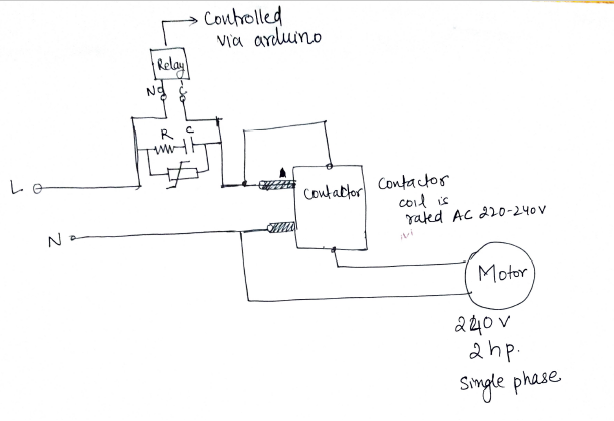
I am trying to control my 2 hp 240AC single phase motor with help of an arduino. Right now it is controlled via a contactor with 220-240 AC coil input voltage with help of NO and NC switches.

Following is what i am trying to achieve: Pardon my poor skills

Circuit Diagram of what I am trying to achieve

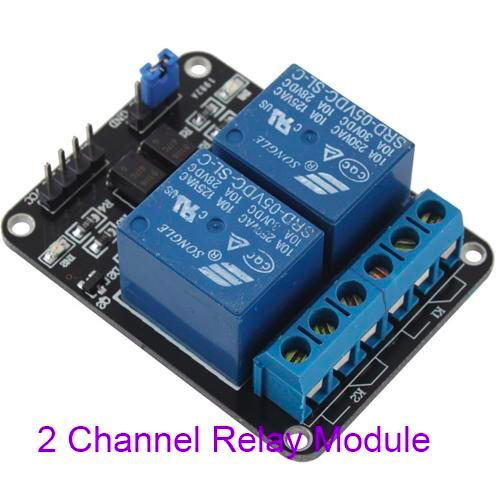
Following is the 10A relay i am planning to use to control the contractor: Generic 5v relay from amazon
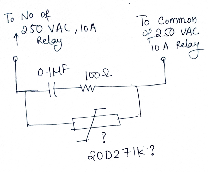
Following is the snubber circuit I have come to accept to the best of my abilities. snubber circuit
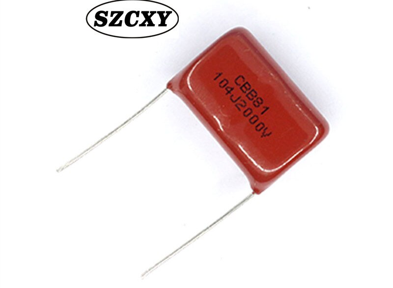
In the snubber circuit I am using 2000V 104J capacitor: Following is the image:

snubber capacitor

From what i could gather I am planning to use 20D271K as the varistor. Following one Varistor

My question is will this work? I apologise for poor circuit diagrams. I will get an electrician to install these. The motor will be switched on 2 times a day for roughly 30 mins.

Help is highly appreciated.

\$\endgroup\$
12
  • \$\begingroup\$ Why the snubber? \$\endgroup\$
    – winny
    Commented Sep 17, 2019 at 16:59
  • \$\begingroup\$ From what i understood, motor being an inductive load, when switched on or off will produce a voltage proportional to the rate of change of current which could be very high. Same would also be experienced at the other end when the coil of contactor discharges. no? So to protect my 10A relay and arduino? \$\endgroup\$ Commented Sep 17, 2019 at 17:04
  • \$\begingroup\$ Are you using an SSR or a relay? \$\endgroup\$
    – Voltage Spike
    Commented Sep 17, 2019 at 17:14
  • \$\begingroup\$ XY problem. What is the motor or inductive current rating of the relay? \$\endgroup\$
    – winny
    Commented Sep 17, 2019 at 17:16
  • \$\begingroup\$ There is a contactor installed to control the motor: something like following: amazon.in/25Amps-4Pole-Contactor-240V-Catno/dp/B07N5LY8JG/… I am using the following relay: I dont seem to able to find the inductive current rating of the 10A relay. The installed contactor has been working fine using NO and NC switches for past 2 years. The 10A relay is: amazon.in/Generic-Channel-Relay-Module-Electronic/dp/B00C59NOHK/… Thank you for your help \$\endgroup\$ Commented Sep 17, 2019 at 17:21

3 Answers 3

2
\$\begingroup\$

Don't switch the load directly! There is already a contactor in the circuit whose One Job is to switch the load. Have your relay switch the contactor coil.

Now you need a much smaller relay, and your snubbing problem is much smaller.

The contactor coil will also be an inductive load and may need snubbing, but nothing like the motor!

\$\endgroup\$
6
  • \$\begingroup\$ That is exactly what I am trying to do. the snubber i have put is between the coil of contactor and the relay which is connected to arduino. I dont have experience in this field that is why I am asking if the circuit that i have drawn above using the resistor (100 ohms), capacitor (0.1uF) and the said veristor is fine or am i making a mistake? one thing i am getting is the issue wont be as pronounced as between the contactor and motor so maybe i could use following snubber? contd.. \$\endgroup\$ Commented Sep 17, 2019 at 19:02
  • \$\begingroup\$ cond.. [snubber from banggood - readymade] (banggood.in/…) \$\endgroup\$ Commented Sep 17, 2019 at 19:02
  • \$\begingroup\$ Relays don't need snubber protection from each other, unless you're overloading the relay. I would be more concerned about snubbing the Arduino side of the small relay so you don't fry the Adruino's outputs. That'll be DC so an overrunning diode would be fine. \$\endgroup\$ Commented Sep 17, 2019 at 19:13
  • \$\begingroup\$ Okay thank you for clearing that up. I have two questions 1. These relays have optical isolation. So if i separately power the relay using a separate 5V source (that is by removing the JD-VCC and VCC jumper), would that work? 2. Since these relays wont be dealing with high current, could i replace them with a solid state relay? contd... sorry for commenting like this \$\endgroup\$ Commented Sep 17, 2019 at 19:27
  • \$\begingroup\$ contd... 2A 240VAC Solid State Relay \$\endgroup\$ Commented Sep 17, 2019 at 19:28
0
\$\begingroup\$

You can’t avoid the EMI of turn on/OFF using a ZVS controlled Triac.

E.g.

https://www.omega.com/en-us/control-and-monitoring-devices/relays/solid-state-relays/p/SSRL240-660

\$\endgroup\$
2
  • \$\begingroup\$ Yes that is an option. But I was hoping to make use of existing components. crydom ssr are my back up. But they cost close to $100 when i convert from INR (Indian Rupee) \$\endgroup\$ Commented Sep 17, 2019 at 19:08
  • \$\begingroup\$ This Omega SSR is only $28. But you probably also want a snubber on the contactor contacts to extend their life. Consult Omron for details \$\endgroup\$
    – D.A.S.
    Commented Sep 17, 2019 at 20:36
0
\$\begingroup\$

Not likely to work well here in my opinion. You have relay and contactor in series. Relay will fail first. The Snubbers ckt is handling both of the kick back., and it needs to be strong enough to cover both inductive loads.

\$\endgroup\$

Your Answer

By clicking “Post Your Answer”, you agree to our terms of service and acknowledge you have read our privacy policy.

Not the answer you're looking for? Browse other questions tagged or ask your own question.