I have a circuit meant to manage a shutter (or a shutter motor to be more precise). The motor has two power lines - depending on which power line one connects power, it moves up or down.
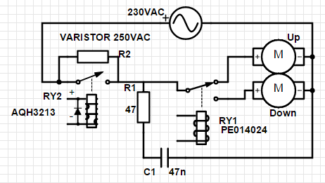
I designed the following circuit to operate the shutter:

RY1 and RY2 are operated via a uC / Mosfets.
I now have the problem that the SSR (RY2) does not turn off even though there is no more current flowing through its control pins (voltage ~20mV, current <1uA). The SSR only turns off when the shutter reaches a final position (fully open or fully closed) - then the motor stops automatically, hence draws no more current on the 230VAC line, and the SSR then stops conducting.
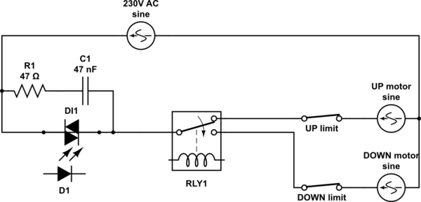
I've already applied a varistor to protect the SSR (R2) because the motor produces some nasty voltage spikes when it reaches an end position. I also added a snubber circuit (R1 / C1) and tried different values (100/100n, 22/100n, 47/47n) to reduce the dV/dt rise across the SSR (as described here), but so far I haven't been successful.
The motor draws roughly 110W.
Is there an "easy fix" for this circuit or should I replace the SSR with a mechanical relay?
Thanks!

