1
\$\begingroup\$

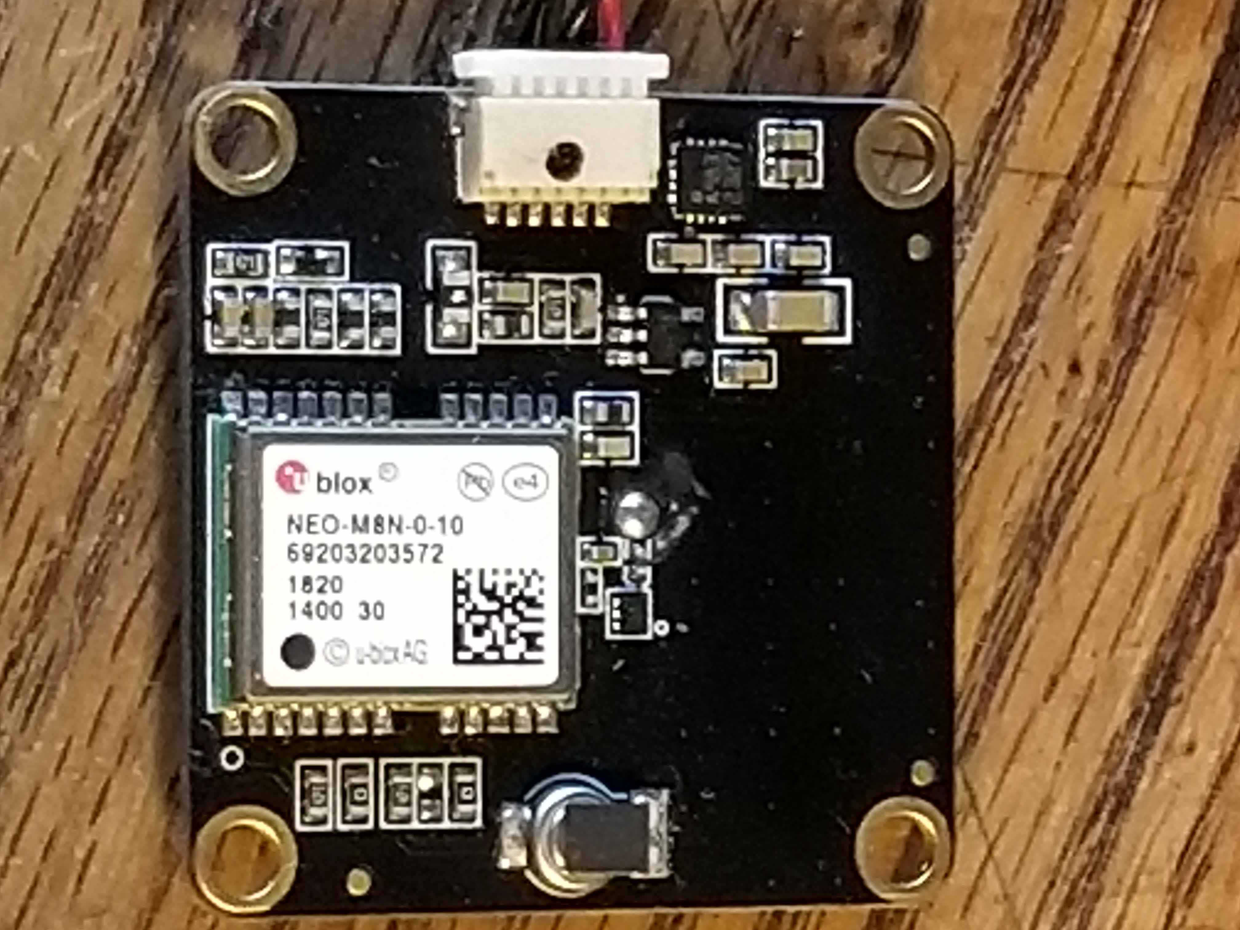
I have a broken GPS/Compass and would like to get it working again.

enter image description here

The device takes 5 Volts input and powers a GPS at a max of 3.6 Volts.

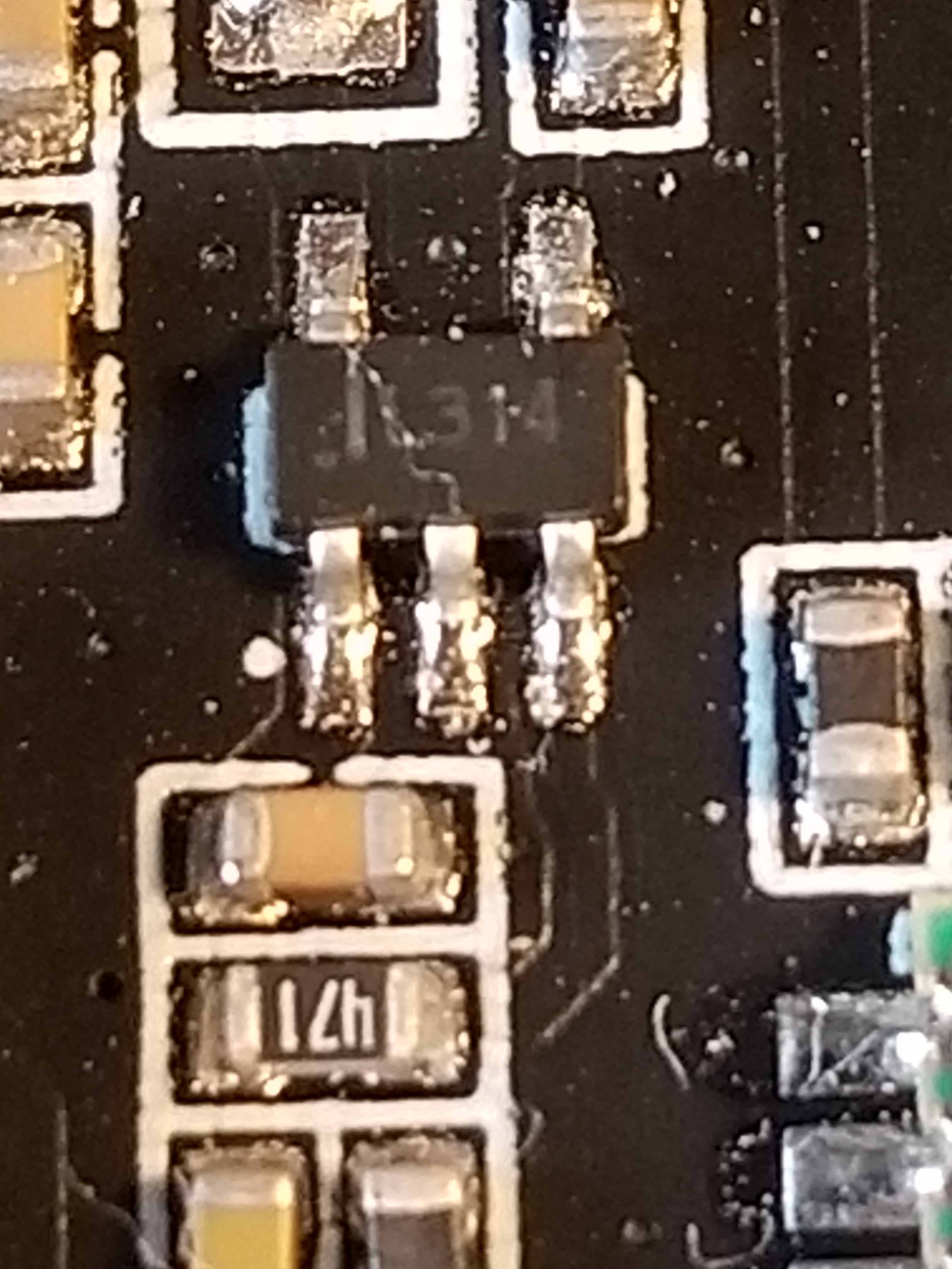
I believe the below chip is bad and I would like to test it. It says IL314. I have no more information on what it is/who makes it? I suspect it is a regulator. Please advise on what this chip is and where I can source a few? Regards

enter image description here

\$\endgroup\$
5
  • \$\begingroup\$ Any regulator with the same footprint will probably work, just aim for a higher then average current... I would also ask how you know that is bad? If it is not putting out any voltage, it could be shut down due to a short circuit somewhere else... \$\endgroup\$
    – MadHatter
    Commented Nov 10, 2019 at 16:05
  • 1
    \$\begingroup\$ That 16 pin QFN package in the upper right also could be the culprit. Solder joint cracking is a popular failure mode. You could try reheating that part of the board and see if it fixes anything . \$\endgroup\$
    – MadHatter
    Commented Nov 10, 2019 at 16:07
  • \$\begingroup\$ I have 2 of these broken devices. I do not know what is bad. I do not know what the IL314 actually is. Something on the board must be a regulator. I was hoping to identify this particular chip, look at its datasheet, and check voltages when in use. On one board, the power light comes on shortly, dims, and goes out. Both boards get warm. When it was on, the gps/ublox was not being fed with a proper voltage, at least on one device. Of course, the gps could be bad and it was shorted internally. I checked the voltage at its vcc. If I can't fix these devices, I will toss them. \$\endgroup\$ Commented Nov 10, 2019 at 23:40
  • 1
    \$\begingroup\$ I would start with a schematic for that board. \$\endgroup\$
    – MadHatter
    Commented Nov 11, 2019 at 3:40
  • \$\begingroup\$ This board was from an online hobby store. When it breaks, you normally throw them if its not under warranty. If you want to try and fix it, you can do what I am trying to do. If I knew what this device is, I can figure out more of that part of the circuit, especially how/if it connects to the gps or nearby components. \$\endgroup\$ Commented Nov 11, 2019 at 14:06

1 Answer 1

1
\$\begingroup\$

It could very likely be a 3.3v regulator as the NEO-M8N chip requires a Vcc of 3.3v. (Is the board's input power 5v ?). You could also power up the board and measure pin 23 (Vcc) of the NEO-M8 chip, (on your board pin 24 is at the corner closest to the red dot, pin 23 is then to the right). Many other designs using the NEO-M8 chip use a similar low power 3.3v regulator (SOT-23-5) to step down from a 5v input.

If Vcc of the NEO-M8 has something lower than 3.3v then perhaps the regulator chip is the main problem, (but if it's 5v you might already have a blown out NEO-M8 chip).

Here is a pdf of a common 3.3v regulator from Micrel, (MIC5235), many similar low power 3.3v regulators have a similar pin out (though not guaranteed). http://www.farnell.com/datasheets/94456.pdf

If you can trace out visually or with a ohm meter at least the Input, Output, and Ground pins on the small chip and they match the common regulator configuration you can be fairly sure it is a 3.3v regulator.

uBlox NEO-M8: https://www.u-blox.com/sites/default/files/NEO-M8-FW3_DataSheet_%28UBX-15031086%29.pdf

\$\endgroup\$
3
  • \$\begingroup\$ The boards input power is 5 volts. I earlier looked up the NEO-M8 chip's datasheet and located its power source(Vcc). I saw that the Vcc pin was less than a volt. I will look at the regulator you forwarded. I had hoped to find the exact datasheet of this chip to eliminate any uncertainty of its pins/operation. \$\endgroup\$ Commented Nov 11, 2019 at 14:13
  • \$\begingroup\$ If you verify the small chip's power and ground lines you might be 99% sure of the chip's function. That doesn't guarantee there are no other problems. If you remove the chip you might also check for shorts on the input or output pins. You might even lift the output pin of the existing chip first to see if it pops up to 3.3v. Similarly you could replace the part with the output pin lifted and verify the 3.3v output. If the output drops after connecting to the board then the NEO-M8 chip might be bad, in that case you may want to scrap the board. Luckily the 3.3v regulators are very cheep. \$\endgroup\$
    – Nedd
    Commented Nov 11, 2019 at 21:42
  • \$\begingroup\$ I just ordered some low melt solder to take it off and try these steps. The output terminal does go to the gps power/vcc. Ground and power are shorted, on the reg input. If I remove the reg, they should not be shorted anymore, i hope. I bought a few regs to try. I have two of these busted gpses ($35 a clip) for my drone. Ill see what happens. \$\endgroup\$ Commented Nov 11, 2019 at 21:51

Your Answer

By clicking “Post Your Answer”, you agree to our terms of service and acknowledge you have read our privacy policy.

Not the answer you're looking for? Browse other questions tagged or ask your own question.