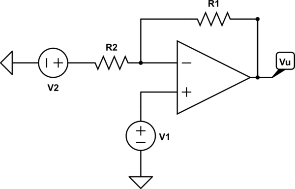
Okay, this may be a stupid question, but at the beginning of my Applied Electronics course they taught us that the differential gain \$A_d\$ of an operational amplifier is ideally infinite; however, in real op amps, we get a limited bandwidth. Which is fine, because it's still very high. My problem raises when I was introduced to common-mode gain and differential-mode gains. In particular, I read that an amplifier subject to common-mode input signals has as a (non-ideal) output a linear combination of its differential mode input voltage mode and its common mode input voltage, i.e., $$A_dv_d + A_{cm}v_{cm}.$$ And for now, everything's fine. But let's consider the practical example in the picture below:

simulate this circuit – Schematic created using CircuitLab
According to what I read, in the schematic above $$V_u=(1+\frac{R_1}{R_2})(v_+-v_-)=\frac{R_1+R_2}{R_2}V_1-\frac{R_1}{R_2}V_2.$$ And since \$\frac{V_1+\frac{R_1}{R_1+R_2}V_2}{2}=v_{cm}\$ and \$v_d=v_+-v_-\$, then \$V_1=v_{cm}+\frac{v_d}{2}\$ and \$V_2=v_{cm}-\frac{v_d}{2}\$. Moreover: $$V_u=\frac{R_1+R_2}{R_2}(v_{cm}+\frac{v_d}{2})-\frac{R_1}{R_2}(v_{cm}-\frac{v_d}{2})=v_{cm}(\frac{R_1+R_2}{R_2}-\frac{R_1}{R_2})+v_d(\frac{R_1+R_2}{2R_2}+\frac{R_1}{2R_2})=\Big(\frac{1}{2}+\frac{R_1}{R_2}\Big)v_d+v_{cm}=A_dv_d+A_{cm}v_{cm}.$$ How are we even just able to say that \$A_d=\frac{1}{2}+\frac{R_1}{R_2}\$? It's limited, fine, but I would've imagined bigger numbers. I guess I can live with a common gain of 1, but since they called both differential gains \$A_d\$, are they seriously the same?
Already from the beginning, I couldn't even understand why would we use $$V_u=(1+\frac{R_1}{R_2})v_d,$$since \$V_u=A_dv_d\$, with \$A_d\$ a big value and, instead, considering an ideal op-amp, as \$A_d\$ approaches infinity, \$V_u=\frac{1}{\beta}v_+=(1+\frac{R_1}{R_2})v_+.\$ But shouldn't \$(1+\frac{R_1}{R_2})\$ be the gain from the non inverting terminal to the output (i.e., closed loop gain), not of the op-amp, or am I wrong? What am I missing? Thank you in advance!
Edit: I am starting to assume that the answer is due to the principle of superposition of effect, i.e., shutting \$V_2\$ off and compute \$Vu\$ due to \$V_1\$, and then shut \$V_1\$ off and compute the overall gain due to \$V_2\$, and adding then the two results together. This could make sense, I suppose, but I can't still figure out why the result is equivalent to \$v_d\frac{R_1+R_2}{R_2}\$, since \$v_d\$ is supposed to be very small and it should therefore be amplified by a high gain \$A_d\$.
Edit 2: fixed typo that made the result wrong, but the question still holds.
Edit 3: fixed the value of \$\beta\$ in the formulas for this schematic. Unfortunately, I chose an unconventional position for \$R_1\$ and \$R_2\$ in the schematic.
