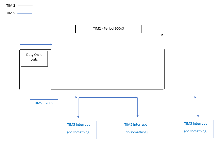
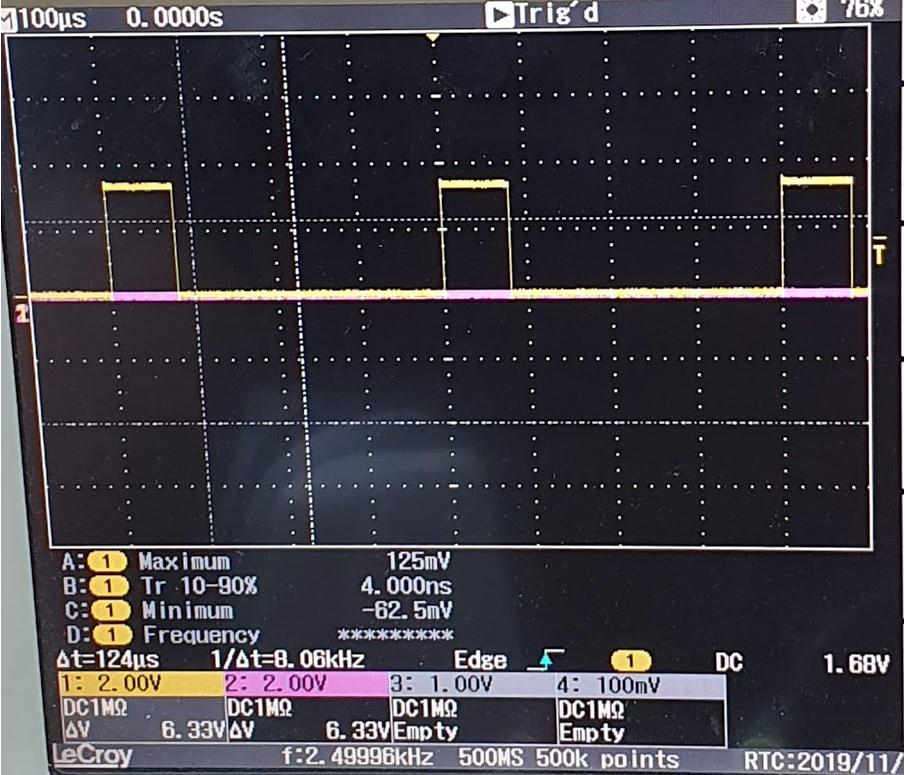
Using an stm32f411re I want to generate a PWM of 20% Duty Cycle with a period of 200uS and simultaneously I want a basic timer to be ticking in the background that sends an interrupt every 70uS (that will then enable an ADC but that's for another day).
Here is a visualisation of what I want:
 I have TIM2 generating the required PWM successfully but the issue comes when I try to add the TIM5 basic timer. Adding a second timer handler in the code for timer 5, timer 2 initialises but it doesn't generate an output. Commenting out the TIM5 handler removes the issue. Strangely commenting out all instances of when TIM5 is used and only having the handler declared at the top of my code (with the tim 5 handler doing nothing) it still causes this issue. My clock speed is 50MHz, I am using STM32CubeIDE. I'm sure it is something simple, but if anyone could take a quick look at the code so I can get TIM5 running alongside TIM2 that would be great.
Here's my main:
#include <string.h>
#include "stm32f4xx_hal.h"
#include "main.h"


void GPIO_Init(void);
void Error_handler(void);
void TIMER2_Init(void);
void TIMER5_Init(void);
void UART2_Init(void);
void SystemClock_Config_HSE(uint8_t clock_freq);
void HAL_TIM_PeriodElapsedCallback(TIM_HandleTypeDef *htim);

TIM_HandleTypeDef htimer2;
TIM_HandleTypeDef htimer5; //This line is causing the issue

UART_HandleTypeDef huart2;

uint32_t clk_freq;
int main(void)
{
    HAL_Init();
    SystemClock_Config_HSE(SYS_CLOCK_FREQ_50_MHZ);
    GPIO_Init();
    UART2_Init();
    TIMER2_Init();
    //TIMER5_Init();
    if(HAL_TIM_PWM_Start(&htimer2, TIM_CHANNEL_1) != HAL_OK)
    {
        Error_handler();
    }
//  if(HAL_TIM_Base_Start(&htimer5) != HAL_OK)
//  {
//      Error_handler();
//  }
    while(1)
    {
        clk_freq = HAL_RCC_GetHCLKFreq();
    }

    return 0;
}


/*
void HAL_TIM_PeriodElapsedCallback(TIM_HandleTypeDef *htim)
    {
        HAL_GPIO_TogglePin(GPIOA, GPIO_PIN_5);
}*/


void GPIO_Init(void)
{
    __HAL_RCC_GPIOA_CLK_ENABLE();
    GPIO_InitTypeDef ledgpio;
    ledgpio.Pin = GPIO_PIN_5;
    ledgpio.Mode = GPIO_MODE_OUTPUT_PP;
    ledgpio.Pull = GPIO_NOPULL;
    ledgpio.Speed = GPIO_SPEED_FREQ_HIGH;
    HAL_GPIO_Init(GPIOA,&ledgpio);
}


void UART2_Init(void)
{
    huart2.Instance = USART2;
    huart2.Init.BaudRate = 115200;
    huart2.Init.WordLength = UART_WORDLENGTH_8B;
    huart2.Init.StopBits = UART_STOPBITS_1;
    huart2.Init.Parity = UART_PARITY_NONE;
    huart2.Init.HwFlowCtl = UART_HWCONTROL_NONE;
    huart2.Init.Mode = UART_MODE_TX_RX;
    if ( HAL_UART_Init(&huart2) != HAL_OK )
    {
        //There is a problem
        Error_handler();
    }


}


 void TIMER2_Init(void)
{
     TIM_OC_InitTypeDef tim2PWM_Config;
     htimer2.Instance = TIM2;
     htimer2.Channel = HAL_TIM_ACTIVE_CHANNEL_1;
     htimer2.Init.Period = 10000-1; //produces a period of 200uS @ a clock of 50MHz
     htimer2.Init.Prescaler = 1;
     if ( HAL_TIM_PWM_Init(&htimer2) != HAL_OK)
     {
         Error_handler();
     }
     tim2PWM_Config.OCMode = TIM_OCMODE_PWM1;
     tim2PWM_Config.OCPolarity = TIM_OCPOLARITY_HIGH;
     tim2PWM_Config.Pulse = 2000;   //Produces a D.C of 20% with a period of 200uS.
     if( HAL_TIM_PWM_ConfigChannel(&htimer2, &tim2PWM_Config, TIM_CHANNEL_1) != HAL_OK)
     {
         Error_handler();
     }


}
 /*
 void TIMER5_Init(void)
{
    htimer5.Instance = TIM5;
    htimer5.Init.CounterMode = TIM_COUNTERMODE_UP;
    htimer5.Init.Period = 64000-1;
    htimer5.Init.Prescaler = 1; //prescaler 1 means timer CNT_CLK is divided by 2. ie. CLK / 1+1

    if (HAL_TIM_Base_Init(&htimer5)!= HAL_OK)
    {
        Error_handler();
    }

}*/
my msp.c
#include "main.h"

void HAL_MspInit(void)
{
    HAL_NVIC_SetPriorityGrouping(NVIC_PRIORITYGROUP_4);
    SCB->SHCSR |= 0x7 << 16; //usage fault, memory fault and bus fault system exceptions
    HAL_NVIC_SetPriority(MemoryManagement_IRQn,0,0);
    HAL_NVIC_SetPriority(BusFault_IRQn,0,0);
    HAL_NVIC_SetPriority(UsageFault_IRQn,0,0);
}

/*void HAL_TIM_Base_MspInit(TIM_HandleTypeDef *htim )
{
    //1. Enable the clokc for TIM 5
    __HAL_RCC_TIM5_CLK_ENABLE();


    //2Enable IRQ of tim5
    HAL_NVIC_EnableIRQ(TIM5_IRQn);

    //3. set up priority for tim5 irq
    HAL_NVIC_SetPriority(TIM5_IRQn, 15, 0);
}*/
void HAL_TIM_PWM_MspInit(TIM_HandleTypeDef *htim)
{
     GPIO_InitTypeDef tim2OC_ch_gpios;
     __HAL_RCC_TIM2_CLK_ENABLE();
     __HAL_RCC_GPIOA_CLK_ENABLE();

    tim2OC_ch_gpios.Pin = GPIO_PIN_0;
    tim2OC_ch_gpios.Mode = GPIO_MODE_AF_PP;
    tim2OC_ch_gpios.Pull = GPIO_NOPULL;
    tim2OC_ch_gpios.Speed = GPIO_SPEED_FREQ_HIGH;
    tim2OC_ch_gpios.Alternate = GPIO_AF1_TIM2;
    HAL_GPIO_Init(GPIOA, &tim2OC_ch_gpios);

     HAL_NVIC_SetPriority(TIM2_IRQn,0,0);
     HAL_NVIC_EnableIRQ(TIM2_IRQn);


}

 void HAL_UART_MspInit(UART_HandleTypeDef *huart)
{
     GPIO_InitTypeDef gpio_uart;
     __HAL_RCC_USART2_CLK_ENABLE();
     __HAL_RCC_GPIOA_CLK_ENABLE();

     //2 . Do the pin muxing configurations
     gpio_uart.Pin = GPIO_PIN_2;
     gpio_uart.Mode =GPIO_MODE_AF_PP;
     gpio_uart.Pull = GPIO_PULLUP;
     gpio_uart.Speed = GPIO_SPEED_FREQ_LOW;
     gpio_uart.Alternate =  GPIO_AF7_USART2; //UART2_TX
     HAL_GPIO_Init(GPIOA,&gpio_uart);

     gpio_uart.Pin = GPIO_PIN_3; //UART2_RX
     HAL_GPIO_Init(GPIOA,&gpio_uart);
     //3 . Enable the IRQ and set up the priority (NVIC settings )
     HAL_NVIC_EnableIRQ(USART2_IRQn);
     HAL_NVIC_SetPriority(USART2_IRQn,15,0);

}
int.c
#include "main.h"

extern TIM_HandleTypeDef htimer2;
//extern TIM_HandleTypeDef htimer5;

void SysTick_Handler (void)
{
    HAL_IncTick();
    HAL_SYSTICK_IRQHandler();
}


void TIM2_IRQHandler(void)
{
    HAL_TIM_IRQHandler(&htimer2);
}
/*
void TIM5_IRQHandler(void)
{
    HAL_TIM_IRQHandler(&htimer5);
}
*/
