0
\$\begingroup\$

If we have a multi-tap transformer like this:

Is it possible to use two of the taps to generate negative voltage and use other taps for positive voltage?

\$\endgroup\$

2 Answers 2

4
\$\begingroup\$

Is it possible to use two of the taps to generate negative voltage and use other taps for positive voltage?

Not that way.

enter image description here

Figure 1. The common GND on the two rectifier outputs places a short-circuit on the transformer via two rectifier diodes.
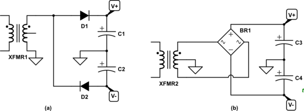
schematic

simulate this circuit – Schematic created using CircuitLab

Figure 2. Two standard ways to do it. (a) Half-wave rectification. (b) Bridge rectification.

\$\endgroup\$
5
  • \$\begingroup\$ Can you please add another example of a transformer with more than 3 taps? \$\endgroup\$ Commented Dec 18, 2019 at 10:14
  • \$\begingroup\$ There's no need to. You just select the three taps you want from the transformer. Your question has no details on what the taps are, other than 0 and 30, and what DC voltages you want. \$\endgroup\$
    – Transistor
    Commented Dec 18, 2019 at 11:28
  • \$\begingroup\$ sorry for lack of information in the question. assuming the transformer has 7 taps and each tap is 5V, I want -5V from one tap and the rest +5,10,...,25V with tap switch. \$\endgroup\$ Commented Dec 18, 2019 at 14:20
  • 1
    \$\begingroup\$ (1) OK, so add that into the bottom of your question where everyone can see it and you'll get an answer. (2) "I want -5V from one tap and the rest +5,10,...,25V with tap switch." Note that you need to explain (a) if you are going to add smoothing capacitors, (b) if you are going to regulate the output voltage and (c) how the regulator setpoint will be switched. (3) How much current you need may also affect the design. In other words, you need to write a proper specification for your power supply before you can design it. \$\endgroup\$
    – Transistor
    Commented Dec 18, 2019 at 15:15
  • \$\begingroup\$ I'll ask those in another question with complete details then, thanks. \$\endgroup\$ Commented Dec 18, 2019 at 16:02
1
\$\begingroup\$

Relative to the lower tap on the secondary marked with a "0" (the reference node), all other taps will produce positive and negative half cycles of voltage and, with the appropriate diode arrangement (plus smoothing capacitors), all other taps can be used to create negative and positive DC voltages.

Is it possible to use two of the taps to generate negative voltage and use other taps for positive voltage?

You can use the same (or different) taps to generate positive and negative voltages because each tap produces positive and negative half cycles that can be rectified into positive and negative DC voltages.

\$\endgroup\$
2
  • \$\begingroup\$ Can you please take look at the added picture to the question to confirm the design? \$\endgroup\$ Commented Dec 18, 2019 at 9:23
  • 1
    \$\begingroup\$ No you cannot do this using full bridge rectifiers because you inevitably short out one or more diodes. You can use one node as your 0 volt reference point and half wave rectify to produce negative and positive voltages from other nodes. Or, use one bridge rectifier straddling a common reference node. \$\endgroup\$
    – Andy aka
    Commented Dec 18, 2019 at 10:03

Your Answer

By clicking “Post Your Answer”, you agree to our terms of service and acknowledge you have read our privacy policy.

Not the answer you're looking for? Browse other questions tagged or ask your own question.