0
\$\begingroup\$

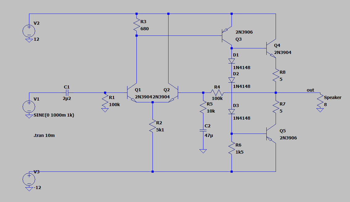
There are lots of similar topics, but I can't find answer that will satisfy me. So, basically I am trying to do a transistor audio amplifier with dual voltage supply (+/-12V). I found circuit like this on some topic:

enter image description here

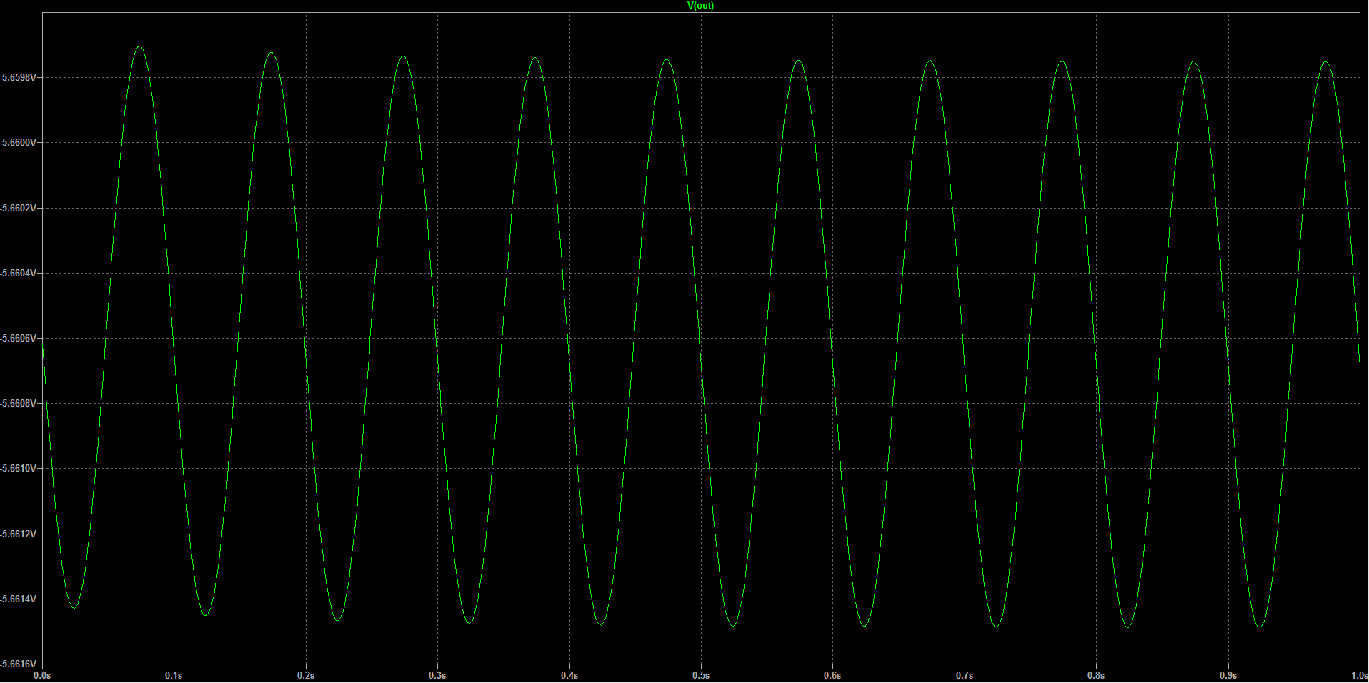
But it doesn't seems to work for me. Here are LTspice circuit with Vout wavegraph: enter image description here

enter image description here

Maybe anyone, knows where is the problem or can show me some simpler circuit with out differential transistor (maybe single transistor with push-pull output).

Best regards


Also, when I finally run this circuit, do You know how to rise the amplification of this circuit(?), for now it is like 30 V/V.


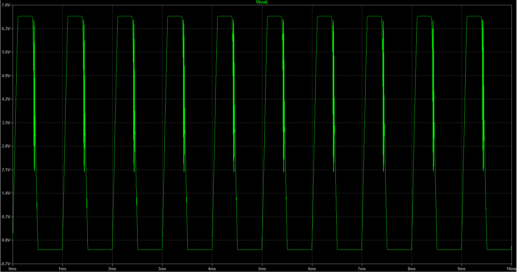
When I add a resistor that simulate speaker, the output waveform starts to get messy again and literally don't know why. enter image description here
enter image description here

\$\endgroup\$
8
  • 1
    \$\begingroup\$ I don't know about a single transistor resulting in a push-pull output. Love to see one, though. \$\endgroup\$
    – jonk
    Commented Jan 8, 2020 at 9:44
  • \$\begingroup\$ Where's R7,R8 in your SPICE version? Is your quiescent current in Q4,5 ... a bit on the large side? \$\endgroup\$
    – user16324
    Commented Jan 8, 2020 at 10:51
  • \$\begingroup\$ Do have any specs ? acceptance criteria? list all \$\endgroup\$
    – D.A.S.
    Commented Jan 8, 2020 at 11:58
  • \$\begingroup\$ No, I do not have, it should just works \$\endgroup\$
    – Rafal
    Commented Jan 8, 2020 at 13:31
  • \$\begingroup\$ No wrong answer. All good engineers use specs. to define threshold of "it just works" or ideal nominal with tolerances ; gain = R4/R5, Vout DC offset referred to input Vo/Gain , stability margin (free of oscillations under load, no load) , Supply range, Load impedance, supply ripple and range., max power (heat rise)= dissipation ( no load , full load power ... heat rise ), THD etc. and Offset adjust. Right now .. excess negative & offset DC idle currents ..... reduce R3 to 525~550 Ohms to null output offset. Reduce losses of R7,R8 to 0.1 Ohms and make Q4,Q5 Darlingtons with 4 diodes \$\endgroup\$
    – D.A.S.
    Commented Jan 8, 2020 at 16:19

1 Answer 1

8
\$\begingroup\$

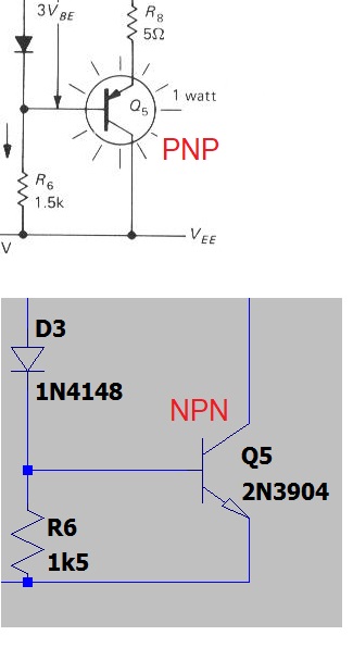
Q5 in the example circuit is a PNP transistor but, in your LTSpice circuit you have used an NPN transistor. This will render it inoperable: -

enter image description here

You have also forgotten the emitter resistors for the output transistors. There may be other errors but these are enough to make you reconsider the simulation.

Addendum

Q3 is incorrect too.

Also, when I finally run this circuit, do You know how to rise the amplification of this circuit(?), for now it is like 30 V/V.

The mid-band AC gain is dictated by the ratio of R4 to R5 plus 1. For the values used, I estimate the mid-band gain to be 31.3. If you require more gain you could lower R5 or increase R4 but, either way, you may start to have problems with gain at the upper frequencies - you'll need to check this out and if you do have a problem it may be easier to apply op-amp gain before the input.

\$\endgroup\$
5
  • \$\begingroup\$ As you've already pointed an error out, another one is that R5 and C2 are connected to V-, not ground. \$\endgroup\$
    – Colin
    Commented Jan 8, 2020 at 9:26
  • 1
    \$\begingroup\$ @Colin probably not a big deal for a simulation because the capacitor will block DC. However, a real amplifier will suffer from noise problems with them connected like that. Thanks. \$\endgroup\$
    – Andy aka
    Commented Jan 8, 2020 at 9:30
  • \$\begingroup\$ Right. Simple mistakes resulting from rush, but even with mentions changes it is not working properly. \$\endgroup\$
    – Rafal
    Commented Jan 8, 2020 at 9:31
  • 1
    \$\begingroup\$ @Rafał look at Q3!!! \$\endgroup\$
    – Andy aka
    Commented Jan 8, 2020 at 9:34
  • \$\begingroup\$ And now it is fine. But it helps with something else. Time to find some goooood glasses. Thanks guys! \$\endgroup\$
    – Rafal
    Commented Jan 8, 2020 at 9:39

Your Answer

By clicking “Post Your Answer”, you agree to our terms of service and acknowledge you have read our privacy policy.

Not the answer you're looking for? Browse other questions tagged or ask your own question.