0
\$\begingroup\$

I have a primary inductor connected to a voltage source with frequencies varying from 100kHz to 15MHz. This primary inductor induces a voltage across a secondary inductor via coupling and I want to amplify that induced voltage and put it through an ADC.

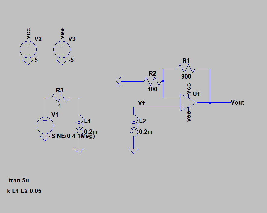
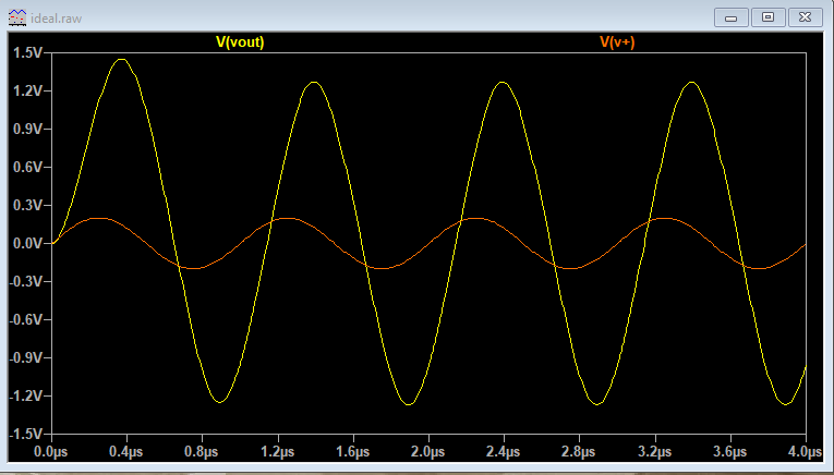
I can do this voltage amplification easily enough with an ideal op amp in non-inverting configuration simulated in LTspice. The two figures below are the schematic and simulation results for the ideal op amp.

Amplification with ideal op amp Simulation result of amplification with ideal op amp

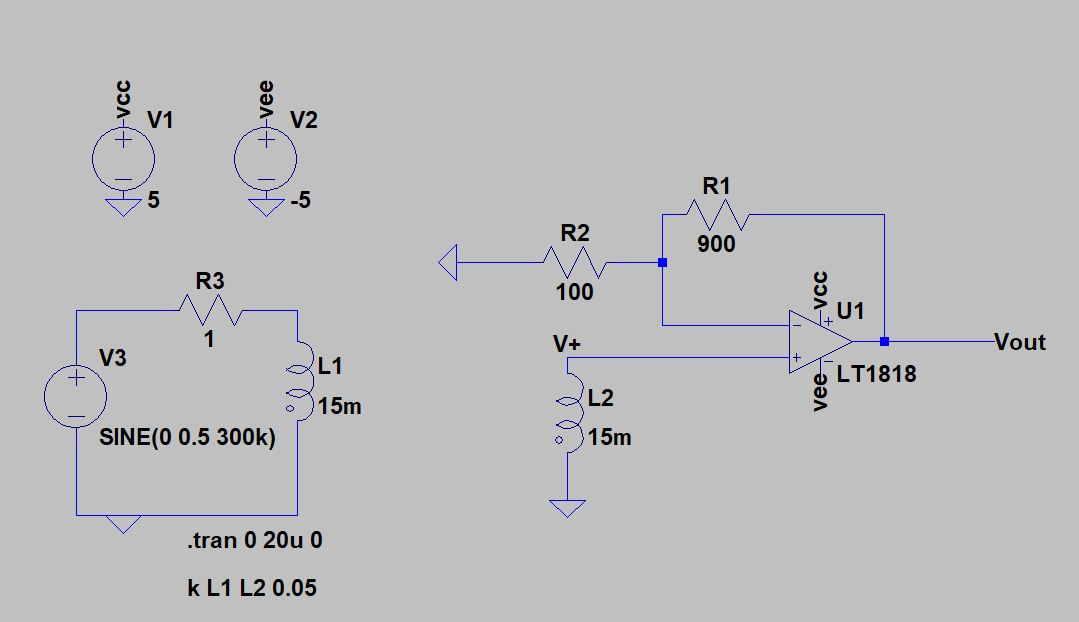
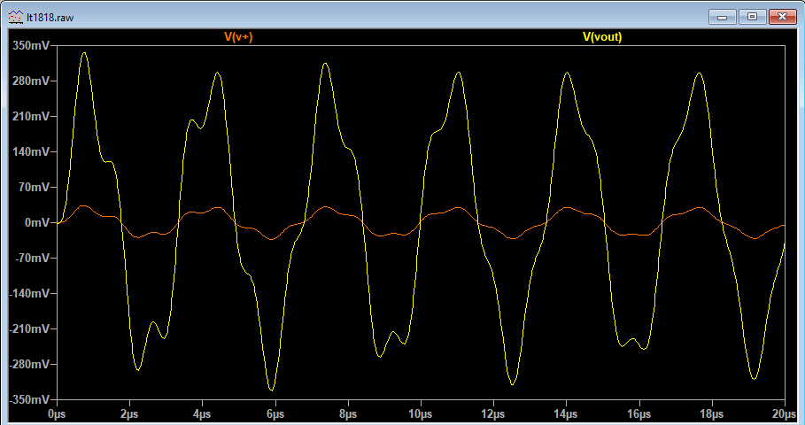
However as soon as I simulate it with a real world model op amp like the LT1818 I get some nasty oscillations on the input node of the op amp which also results in oscillations of the output node. These oscillations always appear even when I vary the frequency in the primary voltage source. I understand that it's probably related to the phase margin of the op amp and the inductive input, but I don't know how to fix it. The two figures below are the schematic and simulation results for LT1818.

Amplification with LT1818 Simulation result of amplification with LT1818

How do I get rid of these oscillations? I have tried another op amp like the LM6172 and I also get similar results. I was also wondering if there is a better way to read the voltage out of a coupled inductor?

Thanks!

\$\endgroup\$
4
  • \$\begingroup\$ You realize most ADCs can't accept bipolar voltages, right? Did you use decoupling caps? Increase the values of your resistors by 5x or 10x so you don't load down your opamp so much. \$\endgroup\$
    – DKNguyen
    Commented Jan 22, 2020 at 2:32
  • \$\begingroup\$ Sorry I don't understand what do you mean by bipolar voltages? I do plan on feeding the output to a fully differential amplifier LMH6552 and then feed the output of that into ADC12040 \$\endgroup\$
    – clostar
    Commented Jan 23, 2020 at 1:27
  • \$\begingroup\$ By bipolar I mean voltages that go both above and below zero volts. A differential amplifier also cannot necessarily accept bipolar voltages. An amplifier with two differential inputs where each inputs can go from 0 to 5V is still unipolar. Differential just means the two inputs can go above and below each other, not necessarily zero. In your case, your diff amp can, but then the voltage it outputs is still bipolar which your unipolar ADC cannot accept unless it is given an offset in some way so it is unipolar which I think you can do by applying a bias to one amp input but you should verify \$\endgroup\$
    – DKNguyen
    Commented Jan 23, 2020 at 1:31
  • \$\begingroup\$ ahh I see! Thank you. I'll be double checking that :) \$\endgroup\$
    – clostar
    Commented Jan 23, 2020 at 4:07

1 Answer 1

3
\$\begingroup\$

You have an L2 inductance of 15 mH that is somewhat lightly coupled to L1 (k = 0.05) hence, the induced voltage in L2 is virtually all in series with the self inductance of L2 (15 mH). This forms a very resonant tuned circuit with the input capacitance of the op-amp (1.5 pF for an LT1818) and that very resonant frequency is 1.06 MHz.

That 1.06 MHz looks in the same ballpark to the ripple artifacts I see in the signal in your picture. You might argue that you are applying a sinewave and hence there should be no harmonics to stimulate resonant signals but, your time-base starts at t=0 and the introduction of a sinewave at t=0 will produce harmonics. Maybe wait for 100 us and see if the ripples start to die down?

It's also worth pointing out that I see some evidence of "artifacts" in the original waveform but I note that L1 and L2 are only 0.2 mH. You have to be consistent with these things and remember that it is likely that your spice sim will have a default value of capacitance attached to every node in your circuit.

\$\endgroup\$
5
  • \$\begingroup\$ Thank you Andy, your answer was very illuminating. I performed FFT and you are correct that it was around 1.06Mhz and it does die down eventually. This leads to another query, is it possible to lower or "remove" the input capacitance so I don't get this resonance effect? Or is the only real solution is to lower the inductance to a smaller amount to move the resonant frequency higher so it doesn't affect the response of slower frequencies of interest? Yep I made a mistake L1 and L2 should have also been 15mH in the ideal case. \$\endgroup\$
    – clostar
    Commented Jan 23, 2020 at 1:24
  • \$\begingroup\$ If you begin the input waveform as a cosine wave it may work because of avoiding inrush currents. Try it and see and let me know. \$\endgroup\$
    – Andy aka
    Commented Jan 23, 2020 at 9:07
  • \$\begingroup\$ Oh what I mean is that the secondary inductor and the input capacitance of the op amp will form a resonant circuit which will produce a varying voltage depending on the transmission frequency which I don't want. So I was wondering if it's possible to reduce impact of resonance? \$\endgroup\$
    – clostar
    Commented Jan 24, 2020 at 6:25
  • \$\begingroup\$ Remember that the frequency response is of a low pass type there is scope for reducing the coil inductances to push the resonant frequency beyond where it matters. Added to this you could put extra resistance in series with the receive coil to reduce peaking effects. \$\endgroup\$
    – Andy aka
    Commented Jan 24, 2020 at 8:38
  • \$\begingroup\$ Okay thank you :) \$\endgroup\$
    – clostar
    Commented Jan 25, 2020 at 1:56

Your Answer

By clicking “Post Your Answer”, you agree to our terms of service and acknowledge you have read our privacy policy.

Not the answer you're looking for? Browse other questions tagged or ask your own question.