2
\$\begingroup\$

I'm working on a product and need somd suggestions:

Which is the best approach to trigger a 5V relay from ESP8266EX WiFi module?

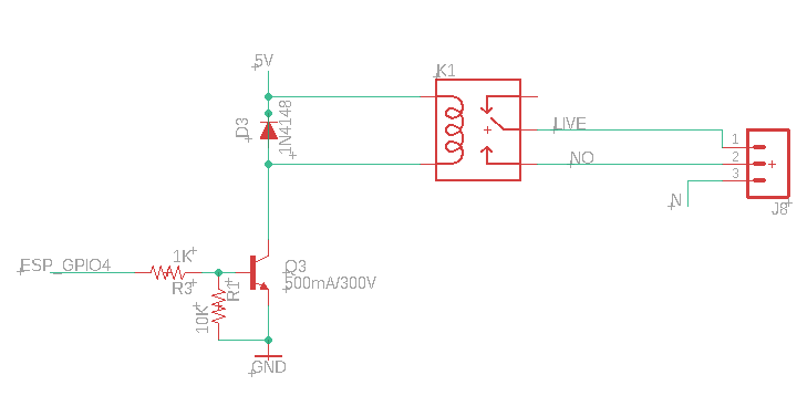
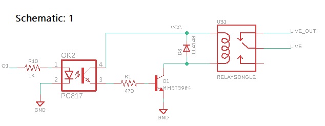
I attached both schematics.

In schematic 1, the relay is triggered using PC817 optocoupler.

In schematic 2, the relay is triggered using MMBT3906 NPN transistor directly.

Schematic1

Schematic 2 Schematic2

Which is best approach in terms of reliability and safe circuit. What are the pros and cons of both approaches?

\$\endgroup\$
10
  • \$\begingroup\$ Can you define your requirements for "reliable" and "safe"? And what will you be using on the LIVE output? Is LIVE mains voltage? \$\endgroup\$
    – awjlogan
    Commented Jan 29, 2020 at 11:22
  • 1
    \$\begingroup\$ Either is OK, but if you are operating the relay at 5V, it's marginally safer to use the coupler since the ESP operates at 3.3V. It'll work without it, but that level of electrical isolation depends on your definition of "safe." However, "reliability" is often gained by using fewer parts. In the second schematic, you could easily replace the BJT with a logic-level FET so you aren't drawing any current from your IO pin. \$\endgroup\$ Commented Jan 29, 2020 at 13:48
  • 1
    \$\begingroup\$ "best approach" would be to replace all that schematics with a single relay driver, like NUD3160 or whatever fits your relay current requirements \$\endgroup\$
    – Maple
    Commented Jan 29, 2020 at 14:10
  • \$\begingroup\$ @awjlogan What I mean with reliable and safe is: In long term perspective, circuit must work and free with any issue to operate the relay. Here, LIVE output is LED Bulbs, Fan (200W) etc. \$\endgroup\$ Commented Jan 30, 2020 at 8:11
  • \$\begingroup\$ @KurtE.Clothier My intention to go with schematic 2 instead of schematic 1 because PC817 opto takes some space in PCB and I have no space for opto but on the other hand, don't want to compromise with "safety" i.e. as opto gives electrical isolation. That's why, I asked that what will be best approach which is safe to trigger the relay without using optocoupler PC817 \$\endgroup\$ Commented Jan 30, 2020 at 8:17

2 Answers 2

2
\$\begingroup\$

The first circuit:

  • is used when the relay VCC is higher than the driver (in your case ESP8266)
  • provides electrical decoupling protection

The second circuit:

  • is good when the relay voltage is the same as the driver's
  • has lower cost than previous circuit
  • you might have problems making the transistor go into saturation when used with higher voltage on the relay
\$\endgroup\$
3
  • \$\begingroup\$ Both can work when the relay VCC is higher than the ESP8266. Unless there is a safety/reliability problem? \$\endgroup\$ Commented Jan 29, 2020 at 13:34
  • \$\begingroup\$ @user253751 As I want to go without PC817 opto because of space problem but don't want to compromise if PC817 gives better safety than schematic 2. What can be alternate or best approach? \$\endgroup\$ Commented Jan 30, 2020 at 8:26
  • \$\begingroup\$ @MohitAgnihotri the second schematic is good for your case \$\endgroup\$
    – Binar Web
    Commented Jan 30, 2020 at 10:33
0
\$\begingroup\$

But for the schematic 1, isnt suppose to be both ground isolate too? I mean, if both have the same ground, all the point of isolation made by the optocouplers, is useless.

\$\endgroup\$
1
  • \$\begingroup\$ I agree with this, it does not look like isolated \$\endgroup\$
    – yunfei
    Commented Oct 27, 2022 at 14:28

Your Answer

By clicking “Post Your Answer”, you agree to our terms of service and acknowledge you have read our privacy policy.

Not the answer you're looking for? Browse other questions tagged or ask your own question.