0
\$\begingroup\$

I'm a beginner in electronics. I am trying to use an optocupler (p621) to switch 12v supply to 5v for digital input.

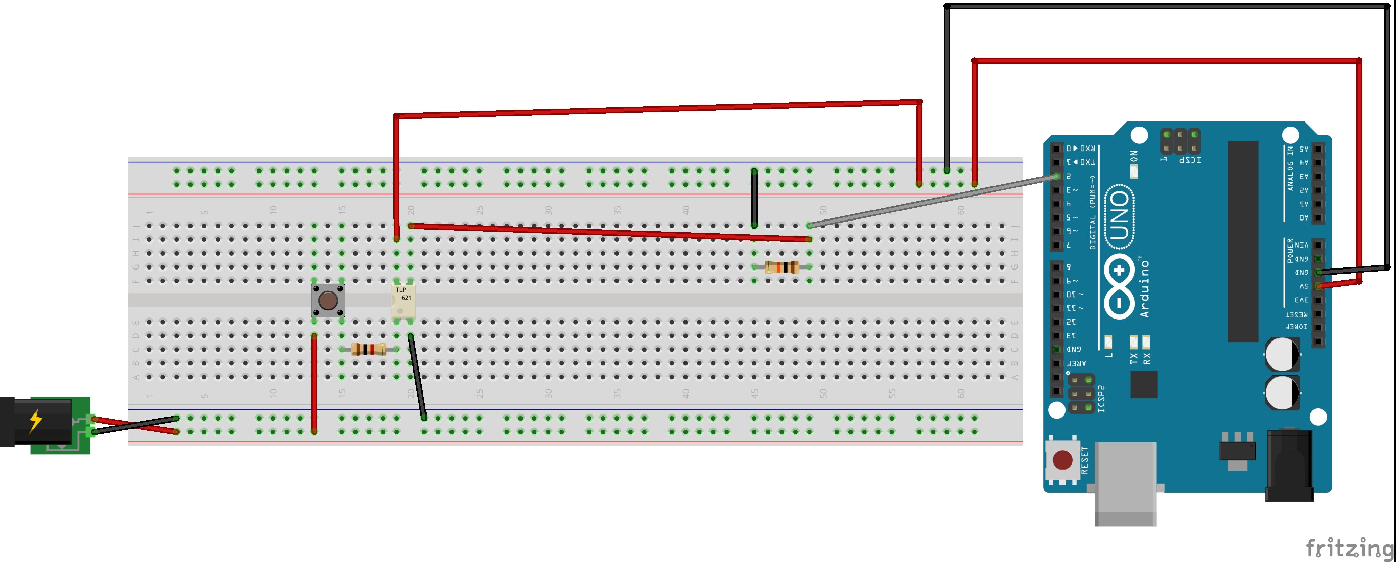
Here is the fritzing diagram

enter image description here

So from the 12v supply I am using 1 1k resistor into the opto P621. So the LED turns on when the button pressed. Then in theory the 5v from arduino connects to pin 2 as a digital input.

Its working fine without much trouble. But even without Optos LED power, the Opto conducts 5v from arduino to the pin.. I've no idea what happens here.

I checked in serial monitor and it says high for that pin randomnly..

So does opto conducts without led voltage or something else wrong in my circuit??

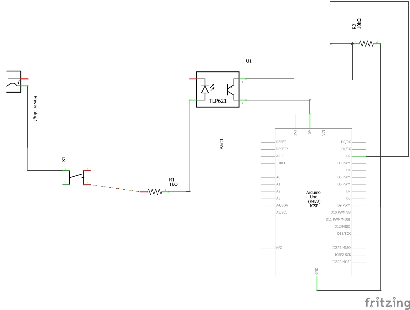
Schematic View

enter image description here

\$\endgroup\$
8
  • 1
    \$\begingroup\$ 1. Share the schematics..Clean hand drawn is also okay.. 2. enable pullup on Pin 2 \$\endgroup\$
    – User323693
    Commented Feb 12, 2020 at 8:15
  • 1
    \$\begingroup\$ No, a proper schematic, not a cartoon of how you built it. \$\endgroup\$
    – Andy aka
    Commented Feb 12, 2020 at 8:22
  • \$\begingroup\$ What happens if you remove the switch from your breadboard? \$\endgroup\$
    – marcelm
    Commented Feb 12, 2020 at 9:49
  • \$\begingroup\$ @marcelm it still shows high.. So 5v conducts even without led \$\endgroup\$ Commented Feb 12, 2020 at 10:05
  • 1
    \$\begingroup\$ in the answer to your previous question you accepted the answer showing a pulll-up resistor. why do you use pull-down? \$\endgroup\$
    – Juraj
    Commented Feb 12, 2020 at 10:18

1 Answer 1

1
\$\begingroup\$

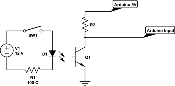
Typically its best to connect the optocoupler in a low side configuration(rather then a high side. The diagram below should help you restructure your circuit:

schematic

simulate this circuit – Schematic created using CircuitLab

Hopefully this way, the internal transistor inside optoucoupler fully turns on when 12V is available and arduino would get 0V. When 12V is not available, Arduino would get 5V at the input.(You can invert the input in logic for the sake of simplicity)

\$\endgroup\$
6
  • \$\begingroup\$ Hi friend, I'm not able to locate the difference between this and my version. Sorry I'm a newbie in electronics \$\endgroup\$ Commented Feb 12, 2020 at 8:42
  • 1
    \$\begingroup\$ @SandeepThomas The emitter pin is grounded, the resistor is connected on the collector side \$\endgroup\$
    – User323693
    Commented Feb 12, 2020 at 8:45
  • \$\begingroup\$ @SandeepThomas A transistor that is NPN should always sync to ground. The TLP621 you are using uses a NPN transistor. (look at the real datasheet : google.com/… ) If you want to use an active high input on your aduino, then you need to get an optocoupler with a PNP (sourcing) transistor. Or simply add a PNP transistor to your existing circuit. \$\endgroup\$
    – Natsu Kage
    Commented Feb 12, 2020 at 9:33
  • \$\begingroup\$ @NoumanQaiser Why would it matter? Normally for a NPN transistor switch, you want to connect the emitter voltage to ground because the base voltage is relative to the emitter and if you connect it the other way around, you get an emitter follower instead. With an optoisolator, this is not a reason because there is no base. \$\endgroup\$ Commented Feb 12, 2020 at 17:24
  • \$\begingroup\$ @user253751 Optoisolators are not all reversible. Some use a single PNP or NPN transistor. A NPN transistor can never be used with the emitter to the positive supply. The base is irrelevant. \$\endgroup\$
    – Natsu Kage
    Commented Feb 12, 2020 at 19:58

Your Answer

By clicking “Post Your Answer”, you agree to our terms of service and acknowledge you have read our privacy policy.

Not the answer you're looking for? Browse other questions tagged or ask your own question.