1
\$\begingroup\$

I need an ESP32 to drive two p-MOSFETs (https://datasheet.lcsc.com/szlcsc/1808131746_Diodes-Incorporated-DMP2104LP-7_C260933.pdf) as PWM controlled output for a motor. As the ESP32 can not deliver enough current, I want to add a simple gate driver for the MOSFETs. Board space is very limited, so a dedicated driver IC is not an option.

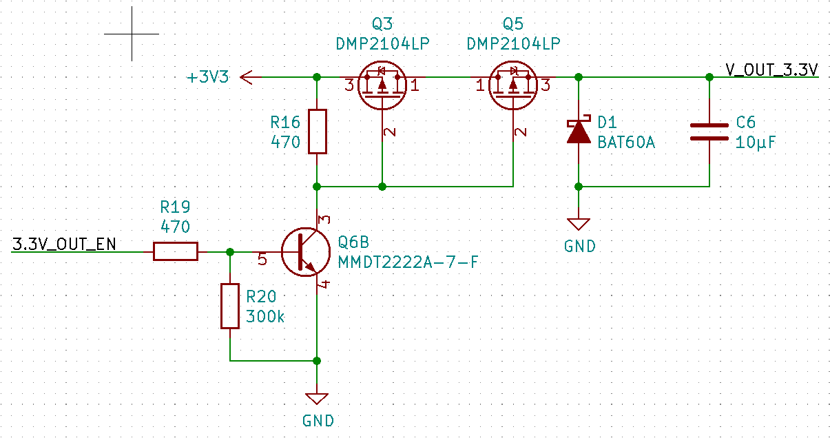
I now have two solutions: First, a driver with a NPN BJT, with a current rating of 600mA, using a MMDT2222A (https://datasheet.lcsc.com/szlcsc/Diodes-Incorporated-MMDT2222A-7-F_C96379.pdf) NPN driver
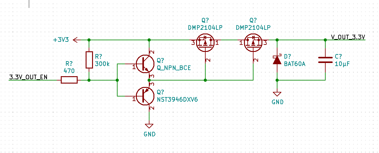
Second, a driver using a NPN+PNP BJT in push-pull configuration, with a current rating of 200mA, using a NST3946DXV6 (https://datasheet.lcsc.com/szlcsc/ON-Semicon-ON-NST3946DXV6T1G_C232646.pdf) PNP+NPN driver
Space wise, both versions fit on the board, but which version is preferable regarding speed and power consumption? The device is battery driven and very small, so power consumption and heat dissipation are important.

\$\endgroup\$
8
  • \$\begingroup\$ "Which version is preferable regarding speed and power consumption?" - Those are often regarded as opposite things, and they depend on your use case. How fast do you need to switch? Given it's pwm for a motor, probably not fast enough for the speed of this circuit to matter much. I'd probably just go for the resistor-transistor method. \$\endgroup\$ Commented Feb 17, 2020 at 17:16
  • 4
    \$\begingroup\$ Why two series MOSFETs? Why no back emf protection? Why not use n channel MOSFET? \$\endgroup\$
    – Andy aka
    Commented Feb 17, 2020 at 17:19
  • 5
    \$\begingroup\$ Which motor? Does the other side of the motor have to be grounded? What is the PWM frequency? Why are you using 2 MOSFETs in series? What is the purpose of C6? \$\endgroup\$ Commented Feb 17, 2020 at 17:20
  • \$\begingroup\$ This is not what you are asking but I suggest you put the FET's with their sources connected together so that the pullup is from gate to source on both of them. You always want your PMOS pullup from gate to source, or your NMOS pulldown from gate to source. Otherwise carefully think through whether everything will work the way you want it to under all conditions. \$\endgroup\$
    – user57037
    Commented Feb 17, 2020 at 19:44
  • \$\begingroup\$ You can also use a CMOS logic gate to drive your FET's. This will switch much harder and faster and use much less power than what you have proposed so far. You can get single logic gates in packages the same size as a transistor package. \$\endgroup\$
    – user57037
    Commented Feb 17, 2020 at 19:50

2 Answers 2

7
\$\begingroup\$

Your NPN transistor MMDT2222A-7-F is in a SOT363-6 package. It lists currently at Mouser at $0.45 in quantity 1.

You can go to the same manufacturer and get the ZXGD3009DY gate driver which is also in the SOT363-6 package. It currently lists at $0.41 in quantity 1.

This ZXGD3009DY (data sheet) offers up a NPN and PNP which can be joined to produce a push-pull type gate driver as you show in your second circuit.

The chip has no space penalty and gives you the faster switching performance for your MOSFETs to save in switching losses power dissipation.

\$\endgroup\$
9
  • \$\begingroup\$ I should have clarified: On the PCB are two PWM controlled outputs, which might be connected at the output terminal. That's why I use two p-MOSFETs for each output, to block the voltage output of one output from the other. That is also the reason why I can't use a dedicated gate driver, as there are no drivers in SOT-363 or smaller that can drive two different MOSFETs. \$\endgroup\$
    – Spatz
    Commented Feb 17, 2020 at 17:42
  • 1
    \$\begingroup\$ @Spatz, the two mosfets have their body diodes pointing in opposite directions. If +3V3 is energized and Q3 is on, then the motor will be energized regardless of the state of Q5 because current will flow through the body diode of Q5. Is that what you want? Or is the diagram in your question inaccurate? \$\endgroup\$
    – user57037
    Commented Feb 17, 2020 at 19:56
  • 2
    \$\begingroup\$ To anyone seeing this, be careful selecting gate driver chips. Not all gate driver chips are actually compatible with microcontroller 3.3V signals; the push-pull types, like the one linked, can require quite a bit of input current to work properly. I've personally gotten trapped by this with one of the ZXG Diodes Inc. gate drivers on a little flyback converter I designed, where my uC couldn't supply enough current to the gate driver. There's some TI ones too, like the UCC27519, which won't work if the gate driver VDD is higher than 3.3V. \$\endgroup\$
    – Ocanath
    Commented Feb 17, 2020 at 20:54
  • 3
    \$\begingroup\$ @Spatz - Well you present one thing in your question and get a fully valid answer only to turn around and say you need something else. Decent engineering work has to be based upon full specifications as to requirements. Half defined projects rarely succeed. \$\endgroup\$ Commented Feb 17, 2020 at 23:59
  • 1
    \$\begingroup\$ @Spatz I am not necessarily saying that this third option is a good one. But I would not use either of the two options you have proposed. They are both not good options. Maybe that is why you see people proposing other ideas. \$\endgroup\$
    – user57037
    Commented Feb 18, 2020 at 18:22
3
\$\begingroup\$

You should put ALL the POSSIBLY relevant information in the question (initially AND now) to save people having to answer spurious questions and/or troll through comments for enlightenment.

The two transistor version is faster in pullup.
It has the disadvantage of losing 0.6V Vbe drop on Vout on both high and low drive. The FET has adequately low Vgsth when turning on,
BUT has Vgsth = -0.45 V minimum at 250 uA so SOME versions of the FET will possibly provide the better part of 1 mA (and just possibly more) when turned off, due to the ~= 0.6V on the gates.
This MAY be acceptable but as you say you have two voltage sources, it may add complexity.

The 1 transistor plus a resistor circuit does not have this issue but PWM turnoff time (470 Ohms + gate capacitances) needs checking.

\$\endgroup\$
2
  • \$\begingroup\$ Thank you for your answer! I think I will stick to the single npn solution then! \$\endgroup\$
    – Spatz
    Commented Feb 18, 2020 at 11:18
  • \$\begingroup\$ @Spatz Note that with thj 1Q 1R solution power consumption when Q is on is about 20 mW in the resistor. IF that matters, make R as large as possible consistent with getting adequate FET turn off speed. | The 2Q cct has essentially zero dissipation except when switching. \$\endgroup\$
    – Russell McMahon
    Commented Feb 19, 2020 at 0:48

Your Answer

By clicking “Post Your Answer”, you agree to our terms of service and acknowledge you have read our privacy policy.

Not the answer you're looking for? Browse other questions tagged or ask your own question.