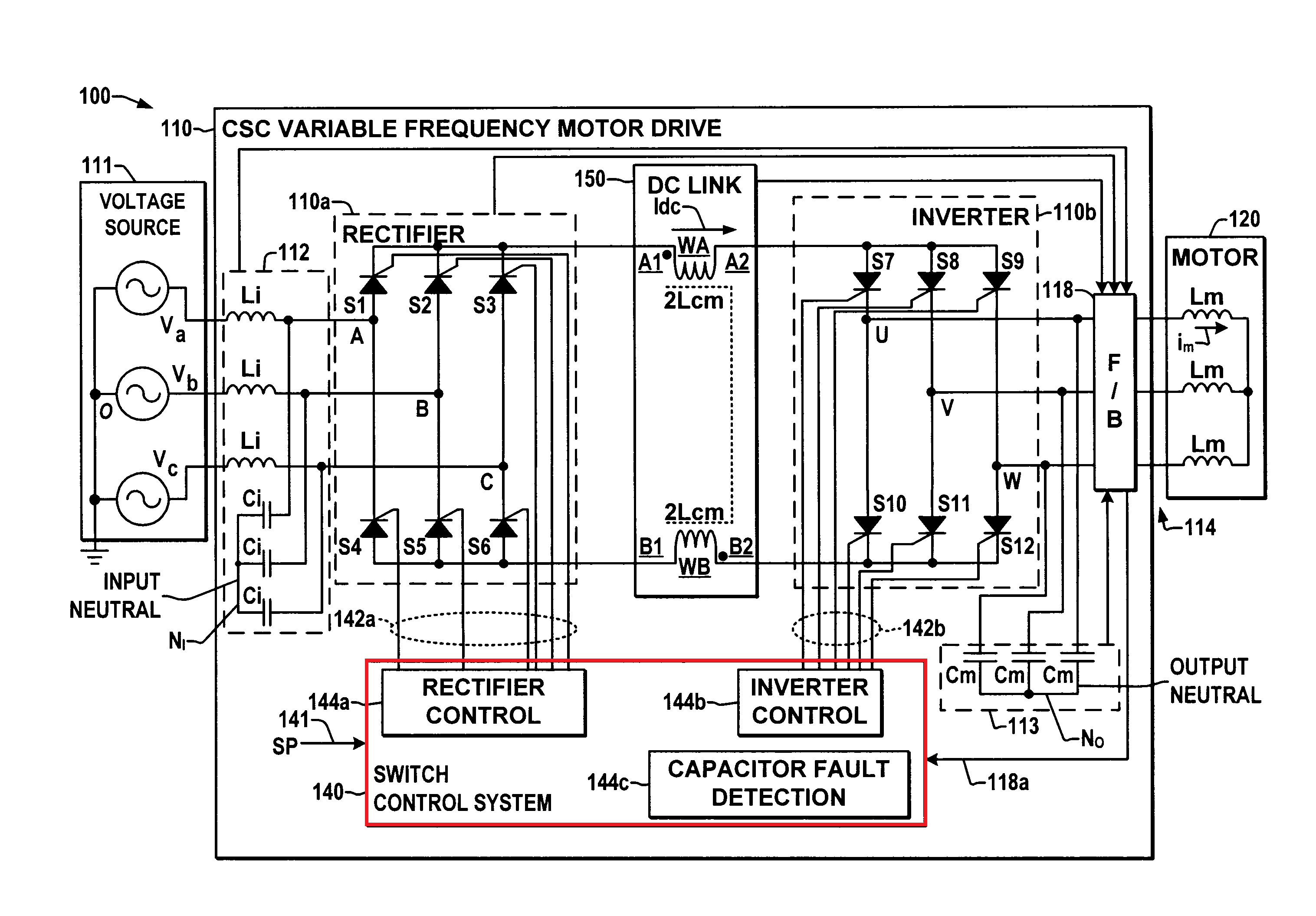
Just a quick one. When looking at schematics for a VFD, I see the same circuits as diodes used in the converter (AC to DC), capacitors in the DC bus and transistors or thyristors used in the inverter to produce PWM to simulate AC output.
Question is, to simulate this AC output, the transistors would have to fire at different times. For 3 phase this would be 6 transistors firing at 60 degrees apart. What controls this firing time? Is there something missing from every diagram I've seen or is there something else I'm missing?
An example of the kinds of schematics I've been looking at is https://www.electronicshub.org/wp-content/uploads/2019/05/Variable-Frequency-Drive-VFD-Building-Blocks.jpg And https://encrypted-tbn0.gstatic.com/images?q=tbn%3AANd9GcQkniY__JYs5TcEJMDSp1t0esI3zMeBTe7ENrK60tw_7PHxrozY
Thanks a lot

