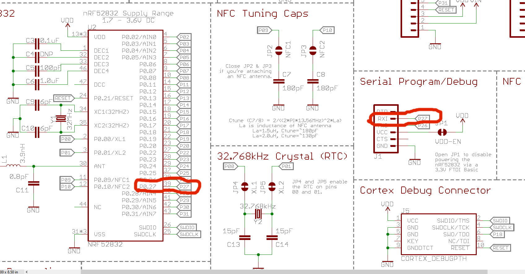
I was setting up a Nordic BLE chip to the UART connection from SparkFun and went to the schematics to figure out how to wire the UART up:
https://cdn.sparkfun.com/assets/learn_tutorials/5/4/9/sparkfun-nrf52832-breakout-schematic-v10.pdf
Personally, I was confused if P0.27 is the pin connect to the UART RX or if it was actually "Pin 39" as per the schematic.
I don't layout lots of boards, but for laying out nets I don't leave any numbers like that. Seems confusing.
I had to monkey around and figure in a project build from Nordic which pins are the UART pins, and spent 15 minutes building and re-building the project till I found it indeed the pin is 27 I needed.
(This is the C code, I needed to guess through a defines list! Is it pin 38/39 or 26/27, UART not working, swap values, check connections and power, blah blah blah, etc.)
#define RX_PIN_NUMBER  26
#define TX_PIN_NUMBER  27
What is the point of the convention with numbers for each net? Does it go back to the physical pin order? Is one convention more common than another on this?
For a smaller footprint I can see leaving the numbers for like a SOT, but for a QFN like this is this really typical?

