0
\$\begingroup\$

I want to build an optical position tracking system based on PSDs (Position-sensitive detectors). I searched online and found this PSD which has a sensitive area of 12 mm*12 mm. My goal is to allow a servo position tracking up to 30 cm or so.

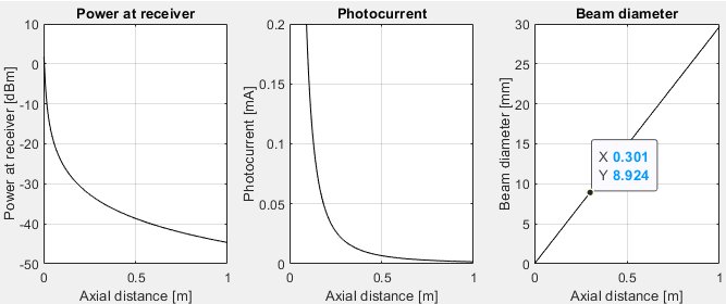
I computed a Matlab model based on some equations I found online and realized that a light source of 1 degree FWHM would produce a beam diameter of nearly 9 mm at an axial distance of 30 cm:

Matlab optical model

This is not acceptable for my application as the PSD allow for 1 mm detectability which is perfect for my needs.

The best light source I found is this one. It has a reasonable package (TO can) compare to other products that do have a narrower beam width but are not as convenient.

Is there a way to decrease the beam divergence by adding some kind of beam expender on a TO can laser diode? Or is there a type of light source that have the same form-factor as this one but with better divergence?

\$\endgroup\$
11
  • 1
    \$\begingroup\$ collimator lens. \$\endgroup\$ Commented Apr 3, 2020 at 17:21
  • \$\begingroup\$ thorlabs.com/… \$\endgroup\$
    – Axis
    Commented Apr 3, 2020 at 17:22
  • \$\begingroup\$ It sounds like you already understand there's a fundamental trade-off between beam diameter and divergence angle, is that correct? It looks like the Hamamatsu part is at least typically quite a bit better than 1 degree, maybe 0.5 degrees FWHM. Is that not accpetable for your application? \$\endgroup\$
    – The Photon
    Commented Apr 3, 2020 at 17:23
  • 2
    \$\begingroup\$ @MarcusMüller, it looks like this device is already quite well collimated. A beam expander or telescope is probably a better fit here. Or choose a more divergent laser, and use a collimator, but then a 2nd beam-expander lens might also be needed to get better than 1 degree divergence. \$\endgroup\$
    – The Photon
    Commented Apr 3, 2020 at 17:25
  • 1
    \$\begingroup\$ Roithner laser tech has the cheapest collimators and mounting tubes to hold the lens and TO package that I have found: roithner-laser.com/ld_mounts.html \$\endgroup\$
    – DKNguyen
    Commented Apr 3, 2020 at 18:38

3 Answers 3

2
\$\begingroup\$

The best light source I found is this one. It has a reasonable package (TO can) compare to other products that do have a narrower beam width but are not as convenient.

Laser diodes need collimating lenses to form a beam. It is counterintuitive, but since lenses Fourier transform light, you actually want a diode with a broad divergence angle. You then place a lens in front of it which gives you a tightly focused beam. If you tried that narrow divergence angle multimode laser diode you linked you will be very disappointed with the beam it produces (which will resemble an LED).

However, all of this is already handled for you if you buy a laser diode module. You can get one that will focus down to hundreds of microns on Amazon or eBay for a few dollars.

I computed a Matlab model based on some equations I found online

That page is talking about Gaussian beams, but the laser diode you have picked (and virtually any practical laser diode with a 1 degree divergence) is a multimode laser which does not produce a Gaussian beam. The overall divergence of multimode beams is complex because they are composed of many different electromagnetic modes that each diverge at different angles.

\$\endgroup\$
3
  • \$\begingroup\$ Thank you for your reply. Two options then, buy a TO can laser diode with a broad divergence and add a collimating lens such as these (thank you for the link @DKNguyen) or as you said look for a laser module that would already embed the lens. \$\endgroup\$
    – Gab
    Commented Apr 4, 2020 at 9:13
  • 1
    \$\begingroup\$ However, caveat emptor on laser diode modules. Make sure you read ALL of the specs. Some, for instance, will only run for limited periods of time before they get too hot, then need a cooldown period. You will be appalled at the price difference between a module you can get on eBay and one from a reputable source such as Edmund Optics. You may also be appalled at what you get from eBay. \$\endgroup\$ Commented Apr 4, 2020 at 14:39
  • 1
    \$\begingroup\$ @Gab For a cheap tip/tilt sensor, I ordered a bunch of random $3 diodes modules online. Generally beam quality was poor, but they could still be focused down to 10s of microns. One problem you may find is that you need a very low power to not saturate your sensor, and many common laser diodes cannot be run low enough while still lasing reliably. \$\endgroup\$ Commented Apr 4, 2020 at 16:45
1
\$\begingroup\$

I suggest you do a centering computation, using the intensities of all the illuminated pixels whatever their illumination. Thus instead of using just the strongest pixel's position on your sensor grid, you take advantage of the dozns of pixels of varying photon flux, and curve-fit.

Your position will have much less RMS error.

\$\endgroup\$
2
  • 1
    \$\begingroup\$ I don't see any indication that the PSD has "pixels". You may be mistaking the linearity grid for a pixel map. \$\endgroup\$ Commented Apr 3, 2020 at 19:01
  • \$\begingroup\$ As @WhatRoughBeast stated, PSDs don’t work that way. There is some formula on the spec sheet that one can use to directly calculate the laser position on the sensitive surface. Your approach with the varying photon flux is however very interesting for photodiode arrays. \$\endgroup\$
    – Gab
    Commented Apr 3, 2020 at 21:52
1
\$\begingroup\$

The sine of 1 degree is .017. .017 x 300 mm is 5.2 mm.

If you look at the data sheet (and are willing to trust the data sheet), it's clear that the beam spread is half a degree or less. Then your spot size will be on the order of 2 mm.

Furthermore, the data sheet for the S1880 states that the photosensitive area is 12 mm x 12 mm. So a 2-3 mm dia beam seems an excellent fit, and you don't need to add any optics to the detector. The PSR resolution is about 150 to 250 um for a 200 um spot size, and increasing the spot size will not change the resolution proportionally, as long as the spot is a symmetrical circle.

What you do need to do is to attenuate your beam. The laser diode you've shown has a nominal power output of 100 mW. The nominal sensitivity of the PSD is 0.6 A/W at 900 nm, with a saturation current of 0.5 mA. Since 0.6 A/W times 100 mW is 60 mA, you'll be overdriving the PSD by a factor of 100, and it's anybody's guess how it will respond.

If you insist that you need a smaller spot size, this is "easily" done by putting a small lens in front of the LD. However, since the laser emitter is (from the data sheet) 200 x 200 um, the same as your desired spot size on the PSR, you want a magnification of 1 or better. For a simple lens, this implies that the lens must be halfway between the LD and the PSR, which means a lens assembly which is 150 mm long. Furthermore, since you are trying to focus the LD spot, rather than collimate, the LD spot will only be in focus at a particular distance, and you will have little leeway in terms of detector distance.

You might be better off trying to collimate the LD using a fairly short focal length lens with a separation equal to the focal length, and then masking the output to a 200 um spot with a precision pinhole - but then you'll have to deal with diffraction issues.

At your level of experience, you must resign yourself to a good deal of messing about and (failed) experimentation. Do not think that you can do a theoretical design and have it work - you just don't know enough. Yet. The process will educate you considerably, though.

Just remember: "Good judgement comes from experience. Experience comes from bad judgement."

\$\endgroup\$

Your Answer

By clicking “Post Your Answer”, you agree to our terms of service and acknowledge you have read our privacy policy.

Not the answer you're looking for? Browse other questions tagged or ask your own question.