3
\$\begingroup\$

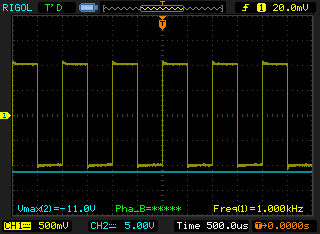
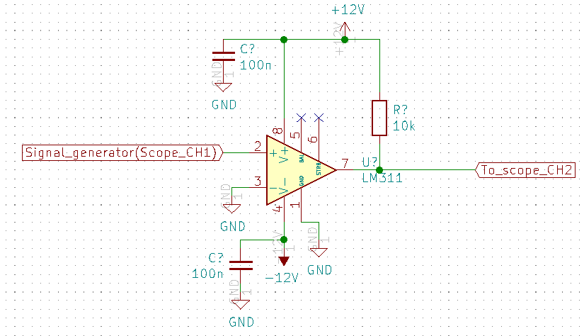
I have wired up the LM311 circuit shown in the figure below. It should work as follows (at least to my understanding), when V+ (pin 2) > V- (pin 3) the output (pin 7) should rise to 12V and when V+ < V- the output should fall to Gnd. I have applied a 1kHz square with an amplitude of 1V swinging around Gnd to pin 2 (V+), see scope image on the second picture. I expect a square wave from 0V to 12V on the output but instead it stays at approximately -12V (CH2 on the scope image), so i.e. at Vee. Even when I apply 12V on pin 2, the output stays at -12V.

My question: Why is this happening? Shouldn't it also produce a square wave on the output? Is there an error in my circuit?enter image description here LM311 circuit as wired up on breadboard
\$\endgroup\$
8
  • \$\begingroup\$ The circuit looks OK to me. \$\endgroup\$
    – Andy aka
    Commented Apr 27, 2020 at 14:23
  • \$\begingroup\$ You have fitted the pullup resistor R? ? \$\endgroup\$
    – user16324
    Commented Apr 27, 2020 at 14:23
  • \$\begingroup\$ Are you sure that you did not swap the pin 2 with pin 3? \$\endgroup\$
    – G36
    Commented Apr 27, 2020 at 14:29
  • 1
    \$\begingroup\$ Vout cannot be equal -11V if pin 1 is connected to GND. \$\endgroup\$
    – G36
    Commented Apr 27, 2020 at 14:36
  • \$\begingroup\$ Yeah I double checked everything, I think the IC is broken \$\endgroup\$ Commented Apr 27, 2020 at 15:50

2 Answers 2

1
\$\begingroup\$

Go over your connections on the hardware and make sure they are connected to the right pins/ wires/ components/etc.

I’ve connected everything together with a circuit I worked on and thought everything was fine, then the circuit is misbehaving. Two hours later I find out a resistor is connected to the wrong pin, changed it and everything was fixed!

\$\endgroup\$
8
  • 1
    \$\begingroup\$ Yeah I reconnected the circuit but it still outputs -12V. I bought this comparator on eBay from China, so I suspect it is just a broken IC. \$\endgroup\$ Commented Apr 27, 2020 at 15:02
  • \$\begingroup\$ Perhaps the IC received electrostatic damage or was a malfunctioned part. Try another LM311 if you have spare. \$\endgroup\$
    – Leoman12
    Commented Apr 27, 2020 at 15:54
  • \$\begingroup\$ Yeah I also thought about that, I tested the whole batch I ordered. None of them seem to work.. \$\endgroup\$ Commented Apr 27, 2020 at 16:05
  • \$\begingroup\$ This may do nothing but try using 10V positive peak input and -10V negative peak input. Keep supplies at 12 and -12V. See if this does help. Perhaps you are too close to rail voltages. \$\endgroup\$
    – Leoman12
    Commented Apr 27, 2020 at 16:57
  • \$\begingroup\$ @Leoman12 Please take care to really answer the question. If you have only suggestions or want to try the OP something, use the comments. \$\endgroup\$
    – Ariser
    Commented Apr 27, 2020 at 17:30
-3
\$\begingroup\$

Pins 5 and 6 are floating. Probably not a good idea.

\$\endgroup\$
1
  • 2
    \$\begingroup\$ They should be kept floating according to the datsheet (if unused) \$\endgroup\$ Commented Apr 27, 2020 at 14:14

Your Answer

By clicking “Post Your Answer”, you agree to our terms of service and acknowledge you have read our privacy policy.

Not the answer you're looking for? Browse other questions tagged or ask your own question.