1
\$\begingroup\$

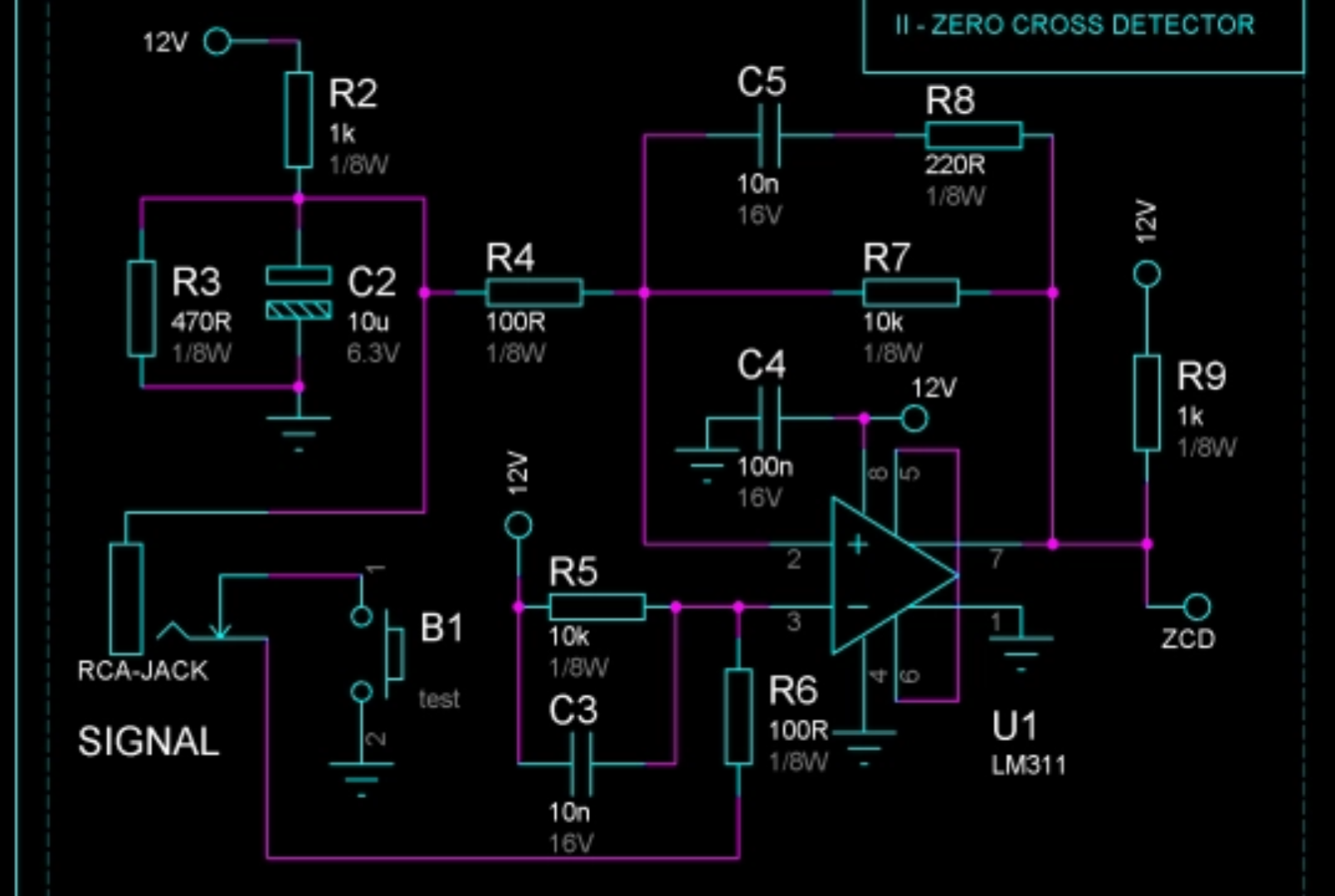
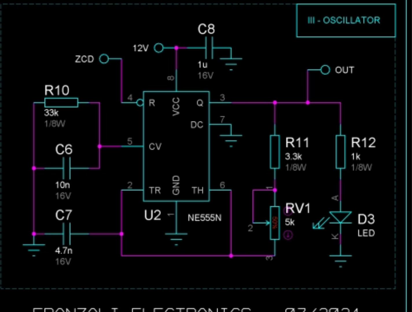
I have no background in electrical engineering other than curiosity; I'm more of a copycat. I have been trying to reproduce this schematic:

enter image description here

555

I have searched the forum but don't see anything remotely close to what I am doing.

I have built it as per the schematic. I did add an LED to pin 7 of the LM311 as an indicator the signal is working (one thing of note: I can only get a signal on output if I press the "normally open" momentary button).

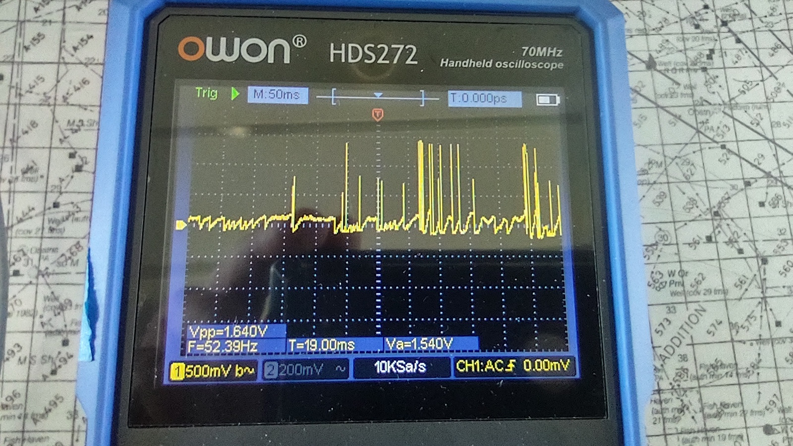
I am feeding the audio through a BT module. When I scope the output I do get a reading:

scope

I have no idea if it's correct. I never used a scope before.

When pin 7 of the comparator is connected to the reset pin of the 555 I should get a polyphonic square wave (I believe) from pin 3, which drives a BC327 transistor which will in turn operate the gate of an IRFP260 MOSFET.

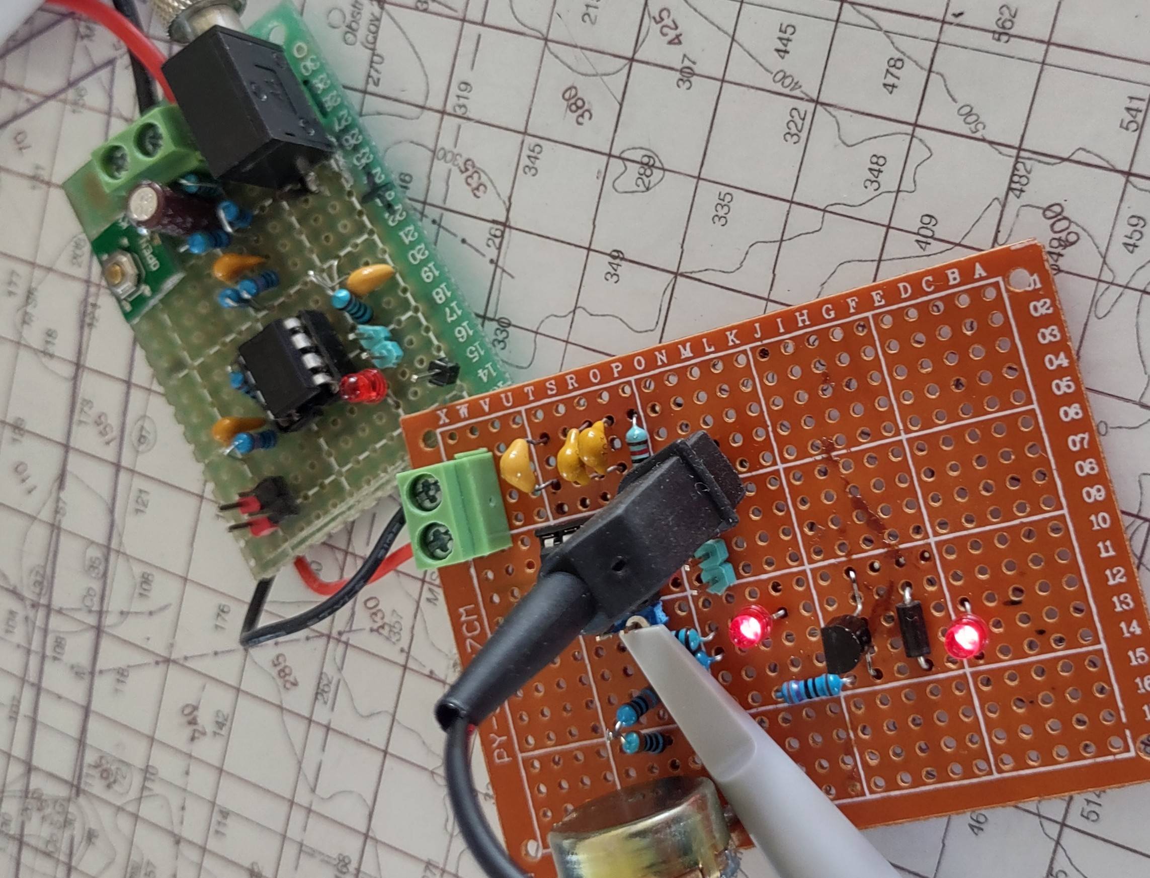
LEDs

The two red LEDs tell me the 555 and the BC327 are both outputting power constantly. They should both be flashing if the reset pin is being triggered properly. I don't know if I need a pulldown resistor on pin 4 or if my output from pin 7 is not switching to low as I understand it should. Any help is appreciated.

Here's a link to the finished project: https://youtu.be/DBukpYea4mQ

\$\endgroup\$
5
  • \$\begingroup\$ Can you show our tell us how exactly you are that LED to the output of the LM311? \$\endgroup\$
    – brhans
    Commented Jul 21, 2022 at 2:43
  • \$\begingroup\$ Do I understand the intention right: The NE555 should stop if there is no audio? \$\endgroup\$
    – Jens
    Commented Jul 21, 2022 at 3:43
  • \$\begingroup\$ Brhans - the led on pin 7 of the LM311 blinks on when the pin goes high. \$\endgroup\$
    – Travalon
    Commented Jul 21, 2022 at 4:43
  • \$\begingroup\$ Brhans - here's a video link drive.google.com/file/d/12kQXnNVK4Ip0ppZAQxJlx8c4cFvmJkAD/… anode to pin 7 cathode to ground. \$\endgroup\$
    – Travalon
    Commented Jul 21, 2022 at 5:25
  • \$\begingroup\$ Jens - yes as I understand it, when there's audio, the led should blink on the 555 as well as the BC327 transistor. When there's no audio it should shut off. The video link shows the LED blinking on pin 7 of the LM311. \$\endgroup\$
    – Travalon
    Commented Jul 21, 2022 at 5:29

2 Answers 2

1
\$\begingroup\$

Perhaps you have a grounding problem.

If the voltage source powering the bluetooth audio device shares a common ground with this circuit, then it could easily upset the conditions that your circuit so carefully sets up.

R2, R3 and C2 establish a more-or-less constant 3.8V at the top of C2. This is the average "centre potential" about which the input signal potential must oscillate.

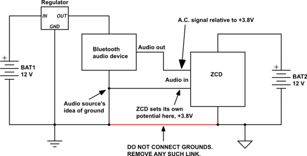
Usually, if a completely independent, electrically isolated audio input signal is presented at the input jack, all will work well, because your circuit holds one side of the input at its own +3.8V, while the other side wiggles up and down around that.

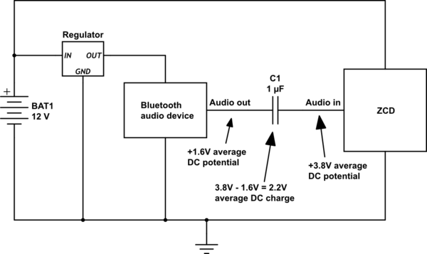
However, if the input source is not isolated, that audio signal will oscillate up and down around its own average D.C. offset. Connecting it to your input jack here will result in a war between two parties over which gets to control the potential at the top of C2. The winner will be the source (+3.8V vs. audio D.C. offset) has the lowest impedance. In layman's terms, the winner is the one who insists the hardest.

To alleviate this problem, you have two solutions:

  1. Completely isolate the audio source from this circuit, by using completely independent supplies (like two separate batteries), and remove any common ground connection between the two parties. This allows the ZCD to adopt its own ground potential relative to the signal source:

schematic

simulate this circuit – Schematic created using CircuitLab

  1. "A.C. couple" the audio source to your circuit's input with a capacitor. This allows the two circuits to share the same ground, because the capacitor will charge to some average D.C. "offset" to "span" the potential gap between +3.8V and whatever average value the audio source has.

schematic

simulate this circuit

\$\endgroup\$
5
  • \$\begingroup\$ The BT does have its own power source but there is a common ground. I'll remove that 1st. Then I'll try the capacitor. I used a headphone jack instead of an RCA plug because that's what I had. Thank you. \$\endgroup\$
    – Travalon
    Commented Jul 21, 2022 at 15:10
  • \$\begingroup\$ Removed common ground and the ZCD is working properly. However, pin 7 is only outputting up to .2Vpp. The 555 datasheet says voltage required to reset is .4 - 1v. I believe this may be my problem. \$\endgroup\$
    – Travalon
    Commented Jul 22, 2022 at 0:27
  • \$\begingroup\$ @Travalon The output of the comparator is emphatically digital, should be close to either 0V or 12V, never in between. There are two possible reasons. Damaged LM311, or its output is being heavily loaded. Disconnect output from 555, so the only things connected to pin 7 are R7, R8 & R9. Make sure pin 1 is grounded. Measure pin 7. Use AA 1.5V cell as input, connected one way to make the input +1.5V, reverse polarity to make input -1.5V. That will place the LM311 in one of two states, steady high or steady low. Measure output (between ground and pin 7) in each state. \$\endgroup\$ Commented Jul 22, 2022 at 3:45
  • \$\begingroup\$ I'm not getting the results you described. Tried 5 different ic's. Even without the aa attached, I'm getting steady high. I'm going to rebuild it from scratch spreading it the components a little for easier troubleshooting. I'll be back with the results. \$\endgroup\$
    – Travalon
    Commented Jul 22, 2022 at 20:01
  • \$\begingroup\$ Got it. I'm not sure where I went wrong in the 1st assembly, but the second with the components spread out works just as the designer intended. Now I need to tune it for better sound and larger sparks. \$\endgroup\$
    – Travalon
    Commented Jul 24, 2022 at 0:08
0
\$\begingroup\$

Rebuilt it and took my time. Used all the same components and didn't crowd them together. Now it works as designed. Don't know how to mark this solved.

\$\endgroup\$
1
  • \$\begingroup\$ Accept your own answer to mark it as solved. \$\endgroup\$ Commented Jul 24, 2022 at 4:57

Your Answer

By clicking “Post Your Answer”, you agree to our terms of service and acknowledge you have read our privacy policy.

Not the answer you're looking for? Browse other questions tagged or ask your own question.