0
\$\begingroup\$

Vcc=5 V, Vin= a noisy input voltage.

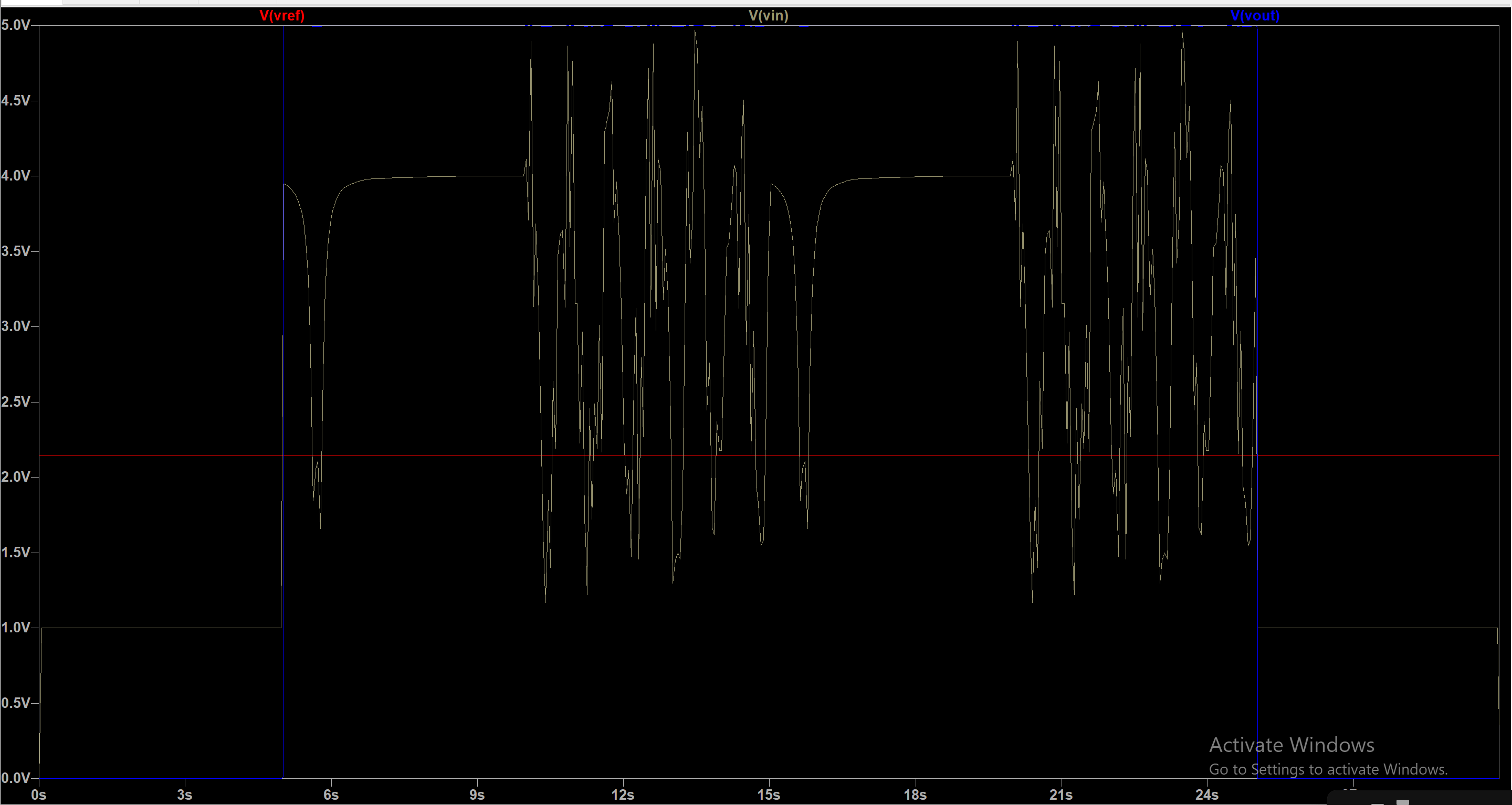
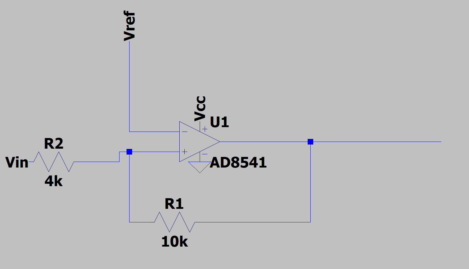
I'm designing a non-inverting Schmitt trigger using a voltage divider. As shown from the image, I designed it using LTpice and I got the desired results.

From the waveform, however, I'm only seeing one threshold which is my reference voltage at 2.143 V. I thought a Schmitt trigger had two threshold voltages? Is there something wrong with this circuit?

enter image description here

enter image description here

I'm having trouble analyzing this waveform. Vref is the threshold; how come I don't see a high threshold and a low threshold?

\$\endgroup\$
4
  • \$\begingroup\$ Look at the +Vin pin. \$\endgroup\$
    – Andy aka
    Commented Apr 30, 2020 at 12:05
  • \$\begingroup\$ Think about how this circuit should work. A Schmitt-trigger has an output that is either low or high. What are the low and high voltages in your circuit. Hint: that has to do with the supply voltages the opamp gets. Then consider each case, when the output is high, what will Vin need to be to make the circuit trip to the other state? Repeat for when the output is low. \$\endgroup\$ Commented Apr 30, 2020 at 12:15
  • \$\begingroup\$ I thought for a schmitt trigger it generate two threshold values? It doesn't generate them, a proper Schmitt trigger has a lower and a higher trip voltage. It is "by design". Imagine if your component values are such that the trip voltages are impossible to reach. \$\endgroup\$ Commented Apr 30, 2020 at 12:17
  • \$\begingroup\$ What is n001? Where is the input in your plot? Vref is not 2.5 V. Label your nets and show us the plot. We need to see both Vin and Vout. \$\endgroup\$
    – user110971
    Commented Apr 30, 2020 at 18:29

2 Answers 2

1
\$\begingroup\$

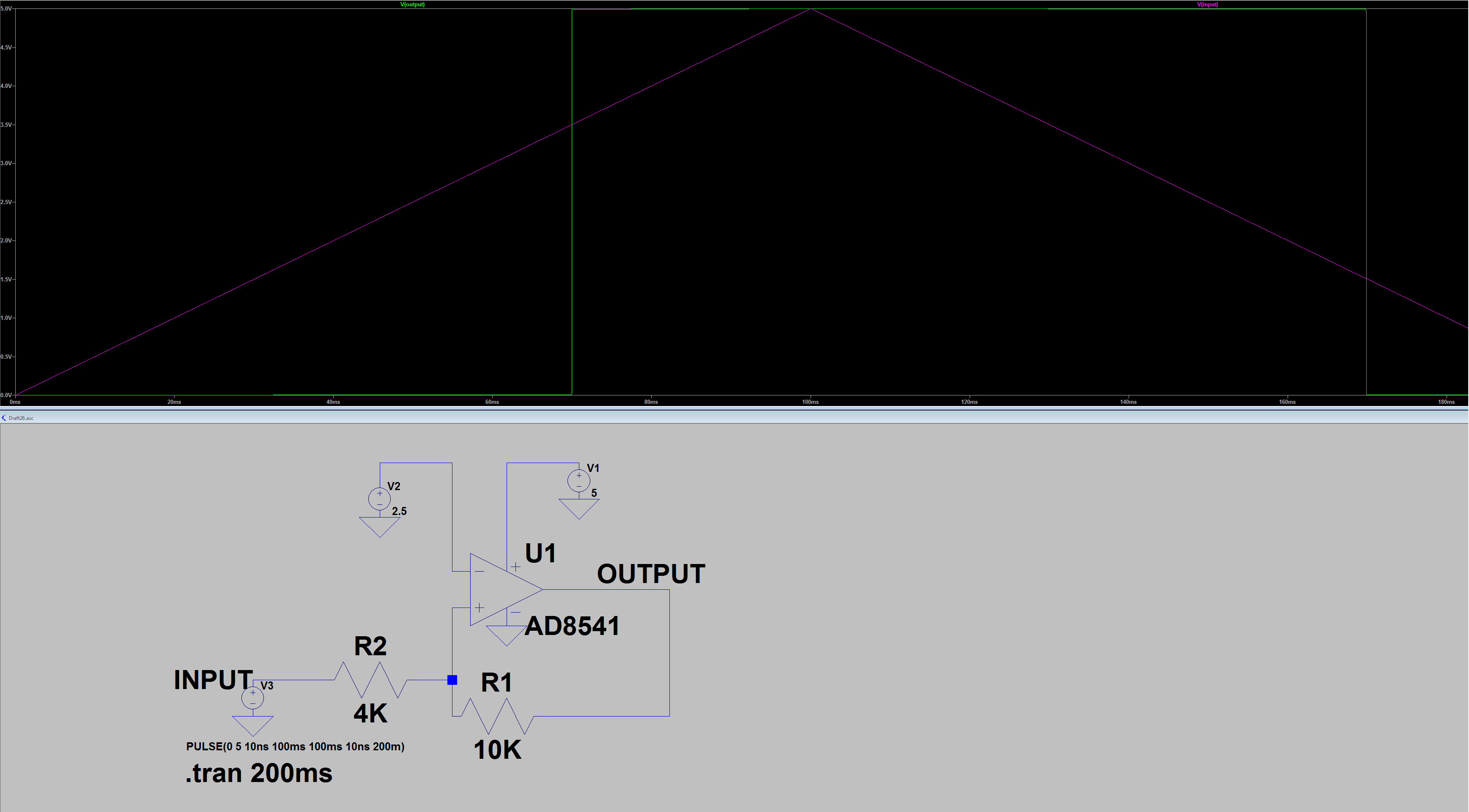
Here is my simulation in LTspice, seems to work just fine:

enter image description here

The switching thresholds are almost exactly at the expected 3.5V & 1.5V, when the input is as slow as I've chosen here.

Using an op-amp as a comparator is not always the best approach (but that's not your problem here). .asc file below.

Version 4
SHEET 1 880 680
WIRE 192 48 128 48
WIRE 304 48 240 48
WIRE 128 64 128 48
WIRE 240 128 240 48
WIRE 192 144 192 48
WIRE 208 144 192 144
WIRE 368 160 272 160
WIRE 384 160 368 160
WIRE 208 176 192 176
WIRE 80 240 16 240
WIRE 192 240 192 176
WIRE 192 240 160 240
WIRE 192 272 192 240
WIRE 384 272 384 160
WIRE 384 272 272 272
FLAG 240 192 0
FLAG 304 80 0
FLAG 128 96 0
FLAG 16 272 0
FLAG 368 160 OUTPUT
FLAG 16 240 INPUT
SYMBOL Opamps\\AD8541 240 96 R0
SYMATTR InstName U1
SYMBOL MiniSyms4\\voltage- 304 64 R0
WINDOW 123 0 0 Left 0
WINDOW 39 0 0 Left 0
SYMATTR InstName V1
SYMATTR Value 5
SYMBOL res 288 256 R90
WINDOW 0 0 56 VBottom 2
WINDOW 3 32 56 VTop 2
SYMATTR InstName R1
SYMATTR Value 10K
SYMBOL MiniSyms4\\voltage- 128 80 R0
WINDOW 123 0 0 Left 0
WINDOW 39 0 0 Left 0
SYMATTR InstName V2
SYMATTR Value 2.5
SYMBOL res 176 224 R90
WINDOW 0 0 56 VBottom 2
WINDOW 3 32 56 VTop 2
SYMATTR InstName R2
SYMATTR Value 4K
SYMBOL MiniSyms4\\voltage- 16 256 R0
WINDOW 3 -59 43 Left 0
WINDOW 123 0 0 Left 0
WINDOW 39 0 0 Left 0
SYMATTR InstName V3
SYMATTR Value PULSE(0 5 10ns 100ms 100ms 10ns 200m)
TEXT -44 322 Left 2 !.tran 200ms
\$\endgroup\$
0
\$\begingroup\$

You are doing something wrong. Are you doing a DC sweep?

When the opamp is in negative saturation, the opamp will switch states when

$$V_\mathrm{in-} \frac{10}{14} > V_\mathrm{ref}.$$

When the opamp is in positive saturation, the opamp will switch states when

$$V_\mathrm{in+} + (V_\mathrm{cc} - V_\mathrm{in+}) \frac{4}{14} < V_\mathrm{ref}.$$

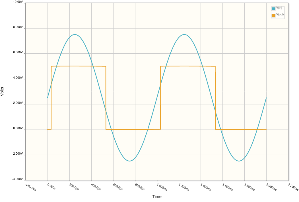
Substituting yields \$V_\mathrm{in-} > 3.5\$ and \$V_\mathrm{in+} < 1.5\$.

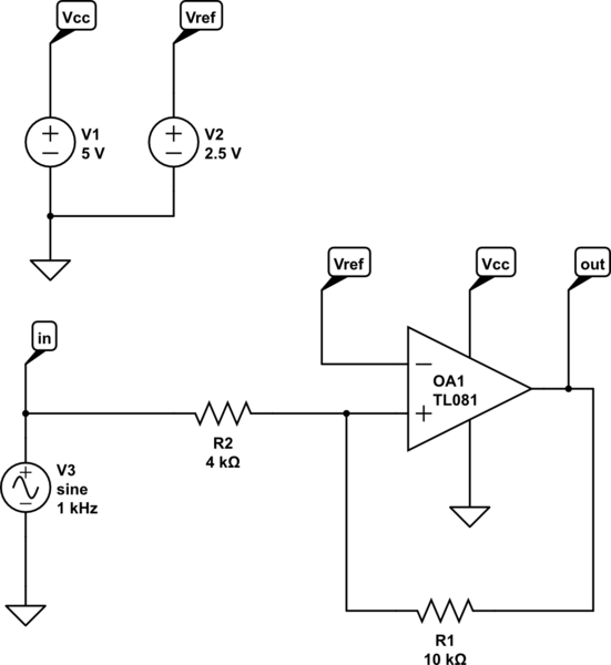
Here is the circuit and the time domain simulation results.

schematic

simulate this circuit – Schematic created using CircuitLab

simulation

\$\endgroup\$
1
  • \$\begingroup\$ I'm using transient. Is there a way to look at the threshold voltages on simulation? I have tried inverting schmitt trigger and I do see the threshold voltages for that but not for non-inverting \$\endgroup\$
    – rikizu
    Commented Apr 30, 2020 at 17:23

Your Answer

By clicking “Post Your Answer”, you agree to our terms of service and acknowledge you have read our privacy policy.

Not the answer you're looking for? Browse other questions tagged or ask your own question.