0
\$\begingroup\$

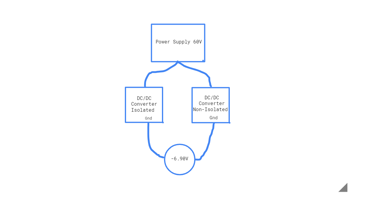
My system is powered by 60 V battery. First converter is 60 V / 12 V isolated, second converter is 60 V / 12 V non-isolated. Two converters power own system component. When I measure the voltage between converters' grounds, the voltage is -6.90 V. Why is the voltage like this? And How can I find the problem?

editing: I measure the voltage between converters seconds(outputs) grounds.

enter image description here

\$\endgroup\$
5
  • 3
    \$\begingroup\$ Why do you expect the two grounds to be at the same potential, and why do think that not being at the same potential is a problem? \$\endgroup\$
    – brhans
    Commented May 9, 2020 at 13:46
  • \$\begingroup\$ I want to read some digital value from one to other \$\endgroup\$
    – hasank
    Commented May 9, 2020 at 13:51
  • \$\begingroup\$ When you ask this type of question you must include your circuit diagram. \$\endgroup\$
    – Sadat Rafi
    Commented May 9, 2020 at 15:24
  • \$\begingroup\$ If you need to transfer digital data, would using optoisolators be an option for you? Or even Ethernet, as that uses isolating transformers. \$\endgroup\$ Commented May 9, 2020 at 18:24
  • \$\begingroup\$ @Jess I am measuring between isolated converter's gorund output and non- isolated converter's ground output with multimeter. \$\endgroup\$
    – hasank
    Commented May 10, 2020 at 7:24

3 Answers 3

1
\$\begingroup\$

If one converter is isolated, there's no reason there should be any specific voltage between its output ground and any other point in the system.

You should be able to connect the two grounds together, which will solve your 'problem'.

\$\endgroup\$
6
  • \$\begingroup\$ I will try to connect the two grounds. But I didn't understand why I measured potential between two grounds yet. \$\endgroup\$
    – hasank
    Commented May 9, 2020 at 13:57
  • \$\begingroup\$ @hasank The reason is given in this answer. If the converter's isolated, there's no reference voltage to act as a ground until you attach one. \$\endgroup\$ Commented May 9, 2020 at 14:07
  • \$\begingroup\$ "Ground" doesn't mean anything if it's floating. \$\endgroup\$ Commented May 9, 2020 at 14:09
  • \$\begingroup\$ First converter is isolated one. So when I connect two converters grounds together, at the same time I connect the 60V ground to isolated connector. I think there is no isolation any of system. Am I right? Is this a problem? \$\endgroup\$
    – hasank
    Commented May 9, 2020 at 14:25
  • \$\begingroup\$ If you connect all three grounds together, then nothing will be isolated. Do you need isolated supplies? If so, you must not connect the grounds together. Any communication between things running on isolated supplies must be via things that maintain the isolaton, like opto couplers. \$\endgroup\$
    – Neil_UK
    Commented May 9, 2020 at 15:00
1
\$\begingroup\$

I think the question you’re asking is, how does an isolated power supply develop a measurable voltage difference between the primary (grounded) and secondary (floating) side?

The answer is, the isolation isn’t perfect. There’s some leakage across the galvanic isolation (transformer in this case). Its measureable using a high impedance meter from floating secondary to primary ground.

You can measure leakage current too - this should be quite low, less than a mA probably for this kind of supply.

Is there a specific reason one part of your load is isolated? A medical device or special instrumentation for example? Then you may need to find or design a supply that has less leakage than the one you’re using.

\$\endgroup\$
1
\$\begingroup\$

If I correctly understand your problem, your converters are connected in parallel for powering their own load and you are measuring the differential potential between the ground of your non isolated converter and the primary ground of the isolated converter ?

How do you do your measurement ? With an oscilloscope or with a multimeter ? I think you are trying to measure the average voltage across the capacitor between the primary and the secondary of your transformer of your isolated converter.

--------------------------E D I T --------------------------
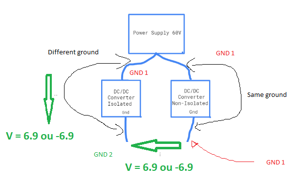
enter image description here

As you can see you are trying to measure the voltage across your transformer isolation, ie the potential difference between the primary ground and the secondary ground.

As @hacktastical said, the isolation is not perfect. Nevertheless I think your measure is bad as you are paralleling a high impedance (the one of your multimeter) and the high isolation of your transformer. Your measure modify the system. It is an "intrusive" measurement. And the voltage value given by the multimeter is not correct as you need to measure an impedance negligeable with respect to the internal impedance of your multimeter for having correct measurement. So it is complicated to say (at least to me) what is the meaning of your voltage measurement.

\$\endgroup\$
2
  • \$\begingroup\$ Yes converters are connected in parallel but not powering same load. They are powering own systems. I measure with a multimeter. \$\endgroup\$
    – hasank
    Commented May 10, 2020 at 7:36
  • \$\begingroup\$ @hasank negative voltage is shown just because of taking the wrong reference. Your question is still not clear. You must show exactly how you have connected the transformer. A complete circuit diagram. \$\endgroup\$
    – Sadat Rafi
    Commented May 10, 2020 at 8:38

Your Answer

By clicking “Post Your Answer”, you agree to our terms of service and acknowledge you have read our privacy policy.

Not the answer you're looking for? Browse other questions tagged or ask your own question.