4
\$\begingroup\$

I once saw the following on an isolated dc/dc converter data sheet and have been doing it ever since with my dc/dc converters, but I wanted to ask to make sure it actually makes sense.

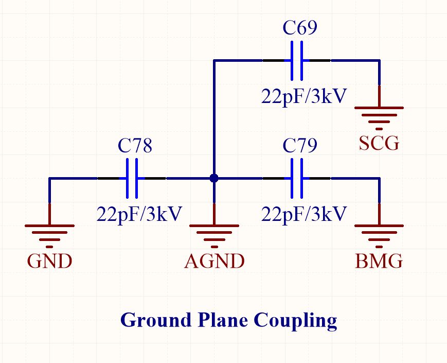
Whenever I have two isolated dc/dc converters, I have been coupling their grounds with a high voltage (~3kV) very low value capacitor like so:

enter image description here

Where AGND and BMG, AGND and SCG, and AGND and GND are all split across switching isolated dc/dc converters.

Does this make sense, and what does it actually achieve?

\$\endgroup\$
5
  • \$\begingroup\$ It provides a low impedance path for very high frequencies. What else can one really say? Do you really have 4 isolated DC-DC converters on one PCB? \$\endgroup\$
    – user57037
    Commented May 8, 2016 at 8:09
  • \$\begingroup\$ There is 5 in total, 2 drive isolation amplifiers, 1 drives a daisy chain of external modules and the other 2 are just different control systems. The application is the battery box for an electric racecar. \$\endgroup\$
    – kvanbere
    Commented May 8, 2016 at 8:19
  • \$\begingroup\$ If your capacitors are not safety rated, doing this means your grounds are no longer being isolated for safety purposes. \$\endgroup\$
    – The Photon
    Commented May 8, 2016 at 15:01
  • \$\begingroup\$ [OT] Why do you need isolated PSUs on an electric racecar? I recall there are some safety rules, one being that everything metallic and partially exposed must be connected to the same, low wrt earth, voltage, so using the chassis as return is usually a no brainer. \$\endgroup\$ Commented May 15, 2016 at 9:33
  • \$\begingroup\$ [OT] The isolated power supplies improve the transient reliability, there are many inductive/bidirectional/capacitive loads, and regarding the chassis, the wiring looms have a lower impedance because the chassis is made of carbon with a honeycomb core, but there is a thin layer of adhesive between the carbon fiber and grounded core. \$\endgroup\$
    – kvanbere
    Commented May 19, 2016 at 4:41

1 Answer 1

4
\$\begingroup\$

Probably best answer is "depending on application". Sometimes grounds are not necessarily "silent" node (for example, powe ground in motor driver), then it should not be coupled with anything else. On the other hand, digital and analog grounds are supposed to be clean, and for that i usually couple them to metal enclosure, which is a thick (related to pcb planes) piece of metal with very low impedance, hence with equal voltage across the whole thing. And of course, the grounds are then coupled between themselves.

\$\endgroup\$

Your Answer

By clicking “Post Your Answer”, you agree to our terms of service and acknowledge you have read our privacy policy.

Not the answer you're looking for? Browse other questions tagged or ask your own question.