0
\$\begingroup\$

I have an off-grid orchard which has a well pump running directly off of a 24v PV array. (27-32v when at full power) Parallel to this direct circuit, I have a buck converter to power a Raspberry pi (via GPIO), which has a switching solid-state relay and a camera to watch the pump and its gauge.

When the Pi triggers the SSR, the voltage coming into the buck drops from 27v to 24v on my multimeter (I don't have an oscilloscope, so perhaps its more of a severe drop), and this causes the output voltage to briefly go to zero, causing the Pi to reboot.

While it's entirely possible this is the fault of the cheap 12v/24v to 5v buck I bought on Amazon, I'm wondering if this is expected, and if so, can I do something like add a capacitor, either on the input or output to buffer this, and keep the pi running.

\$\endgroup\$
2
  • \$\begingroup\$ Update: My observations while on site weren't captured accurately. Turning the motor on is actually fine, however it's switching it off that's causing inductive flyback, which is likely triggering overcurrent protection and cutting off the Pi's power. So next weekend when I'm at the site, I'll add a 45v/20A rated Shottky diode, in reverse bias, and I bet that will solve the problem. \$\endgroup\$
    – Excalibur
    Commented May 13, 2020 at 4:24
  • \$\begingroup\$ It doesn't need to be a schottky diode - virtually any diode capable of handling the load current for a few tens of milli seconds will be fine. In fact I'd stay away from schottky diodes on this job because of high leakage current at high temperatures. \$\endgroup\$
    – Andy aka
    Commented May 13, 2020 at 8:57

3 Answers 3

3
\$\begingroup\$

To keep the input voltage to the buck converter from dropping down to some really low value during the inrush current period of the 150 watt motor, use a diode and capacitor. This will "hold-up" the voltage at the input to the buck circuit despite it dropping down across the motor. The diode gets reverse biased during this short period and therefore the motor load doesn't discharge the capacitor.

But, you have to choose a capacitor that is sufficient. For instance, if the buck regulator will work down to (say) 8 volts without a problem, then you can start to calculate the hold-up capacitor. Based on the pi taking (or needing) say 1 amp we can say: -

$$I = C\dfrac{dv}{dt}$$

Where dv is the permissible drop from 24 volts to 8 volts i.e. 16 volts and dt is the the inrush time for the motor (say) 2 seconds hence: -

$$1\text{ amp} = C\dfrac{16 \text{ volts}}{2\text{ seconds}}$$

C therefore equals 125,000 uF or above.

The numbers used above are my guesstimates and may not bear much resemblance to the real values needed by the buck regulator or the pi current.

\$\endgroup\$
1
  • \$\begingroup\$ Thanks Andy aka, this adds another useful tool to my toolbelt! It appears that my problem is just inductive flyback when turning off the motor, which makes sense, and is easily fixed with a good sized shottky diode. Great explaination and helpful walkthrough of that capacitance equation. I'll remember that. \$\endgroup\$
    – Excalibur
    Commented May 13, 2020 at 4:29
1
\$\begingroup\$

If the power converters & supplies you have are well-made, they should already have capacitors in parallel between the +5V and ground lines to smooth any jumps in voltage. However, you can definitely add a cap as close to the RPi as possible to smooth out the voltage even more. The problem is also coming from the RPi triggering a power hungry device, so you may be able to add an inductor in series with the device to slow down power surges.

An alternate (and pricier) option is to use an un-interrupted power supply for the RPi power, or connect a battery pack that is both continuously 'charging' the pi, and being charged by the buck you already have. The battery method isn't recommended due to the current draw from the RPi but is a possible short-term fix depending on the type of battery.

\$\endgroup\$
4
  • \$\begingroup\$ Thank you, Nate. If it helps, the load is a big well pump, which can use up to 150w, so on/off is a pretty large change in load. An inductor is an intriguing idea, although I need to ensure anything I add doesn't reduce reliability, since this is a distant, remote site. I'll look into capacitors near the pi, since that might be a simpler fix. \$\endgroup\$
    – Excalibur
    Commented May 11, 2020 at 22:28
  • \$\begingroup\$ Also, you touched on a good point I hadn't considered. Turning the motor on may not be as much a problem as turning it off, given that it's a large motor, and inductive load may be triggering overcurrent protection within the buck converter. If this is the case, I should carefully add some methods of preventing back-current from the motor, inductors/diodes, etc. But I must admit that I only enough here to be dangerous. ;) \$\endgroup\$
    – Excalibur
    Commented May 11, 2020 at 22:46
  • \$\begingroup\$ That is definitely a good point with the back-current. A diode in series with rating for enough current wouldn't be a bad idea. \$\endgroup\$
    – nate
    Commented May 11, 2020 at 22:53
  • \$\begingroup\$ The battery approach might work well with a "24v" lead-acid battery across the panel (don't forget diode). They last longer and are more tolerant of float charging than Li-ion. \$\endgroup\$
    – pjc50
    Commented May 12, 2020 at 8:48
1
\$\begingroup\$

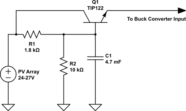
The buck converter apparently can't keep up with the abrupt change in input voltage. A cap probably won't be enough to smooth the voltage drop, but if you are willing to build a circuit, you could put in a capacitance multiplier to smooth it much more effectively. This solution could work if the voltage drop is not in fact much more severe than a few Volts.

This circuit is a common ripple rejection circuit. Q1 is a Darlington transistor. R1 and R2 form a low-pass filter with C1, which prevents abrupt changes at the collector of Q1 from passing through to the emitter. If the PV array output steps abruptly by 3V, it should take 10 seconds or so for the Q1 emitter output to make that transition with the component values shown below. That should give the buck converter plenty of time to adjust.

The RPi and camera probably draw somewhere in the ballpark of 200 mA at the input of the buck. With these component values there is about five Volts across the Q1 collector-emitter terminals, so Q1 will dissipate about a Watt. It should be able to handle without a heat sink, but it might be a good idea to put one on in case the Pi & camera draws more than that.

The disadvantage of this approach, apart from the complexity, is that you give up a Watt or so to the ripple rejection circuit.

schematic

simulate this circuit – Schematic created using CircuitLab

\$\endgroup\$

Your Answer

By clicking “Post Your Answer”, you agree to our terms of service and acknowledge you have read our privacy policy.

Not the answer you're looking for? Browse other questions tagged or ask your own question.