3
\$\begingroup\$

I would like to control one of these 8-relay boards with my RPI GPIOs.

Please check the below schematic - it shows the parts involved for one of the 8 relays. JD-VCC is connected to the 5 V of the RPI, because the board uses 5 V relays, that's fine.

I'm unsure if I should use 3.3 V or 5 V for VCC (e.g. driving the optocoupler). I found several tutorials in the internet, some of them say 5 V, some 3.3 V.

Since some of the tutorials recommend using 5 V for VCC. I was asking myself if that damages the RPI's GPIO, because as far as I know, they are not 5 V tolerant. However, measuring the voltage on the IN1 using my multimeter results in 3 V. I guess this is due to the optocoupler diode forward voltage and also the forward voltage of the IN3 LED.

I'm not a professional EE, just a tinkerer, and I would just like to have the assumptions mentioned above confirmed. Is it safe to use 5 V for VCC?

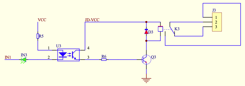
schematic

\$\endgroup\$

2 Answers 2

1
\$\begingroup\$

You must use +3.3V for \$V_{CC}\$.

When using +5V for \$V_{CC}\$, it's only the green LED that's saving you. It's by sheer luck that LED current drops below some "threshold" level to switch Q3 off, since without that green LED, there would still \$5.0V-3.3V=1.7V\$ across R5 and its LED.

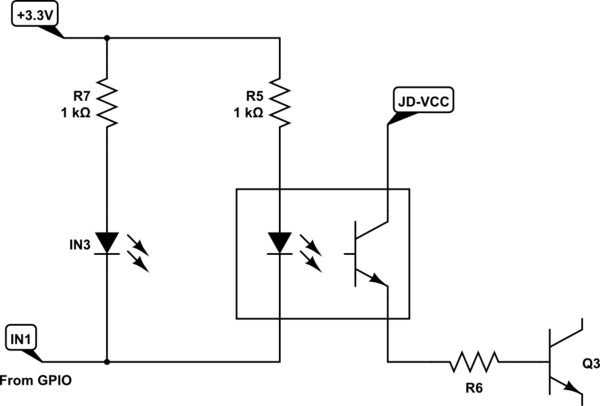
If you want LED current to be truly zero when GPIO output is high at +3.3V, then there must be no voltage across R5 and its LED, which means that \$V_{CC}\$ must also be +3.3V. Also, if you want an indicator LED, power it directly from the GPIO output, not in series with the opto-coupler LED:

schematic

simulate this circuit – Schematic created using CircuitLab

In this way, diode IN3 is no longer interfering with the potential difference placed across R5 and its own LED.

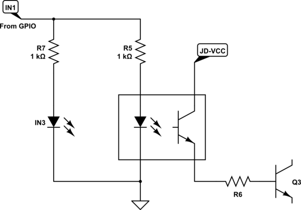
You could avoid this ambiguity altogether, and have the GPIO source current for the LEDs:

schematic

simulate this circuit

This would invert the meaning of IN1 (relay is now off when IN1 is low), but that's an easy fix in software.

\$\endgroup\$
0
\$\begingroup\$

The IN must be pulled down to ground to turn on. It must be pulled up to VCC to turn off. At 3.3V IN there is still a difference of 1.7V and that may result in current through the optocoupler so it may not turn off. And when HiGH-Z or ground the gpio would send 5V potential through it.

As long as you are sure VCC and JD-VCC are isolated, then VCC should be 3.3V for the RPI to work with it. But it could also not be enough for the opto coupler and the status led to light up. Alternatively would can use a NPN transistor (2n3904 is fine) from the RPi gpio to control the Opto. This would isolate the IN so you can power the relay board from 5V.

\$\endgroup\$
7
  • \$\begingroup\$ Thanks for your reply, I got most of your explanation except for the High-Z or Ground, when there still is a chance of 5V going through the GPIO. In what situation this would be the cause? Are the GPIO of the RPI in such a state during boot? Sorry to bother you \$\endgroup\$
    – John
    Commented Jun 4, 2020 at 14:47
  • \$\begingroup\$ I believe they are High-Z, high impedance or input mode during boot I am unsure. \$\endgroup\$
    – Passerby
    Commented Jun 4, 2020 at 15:17
  • \$\begingroup\$ I'm just wondering why my multimeter measures just 3V at the "IN" point while the cable is not yet connected to the GPIO. Doesn't that mean there is a maximum of 3V coming to the GPIO no matter in what state the GPIO is, because there are the two diodes in line? \$\endgroup\$
    – John
    Commented Jun 4, 2020 at 15:27
  • 1
    \$\begingroup\$ I temporarily connected VCC to 5V and did some current measurements. If my GPIO is pulled to Ground, 2.1mA are sinked into the RPI, if I switch the GPIO to High, no current is flowing and the relay turns properly off. \$\endgroup\$
    – John
    Commented Jun 4, 2020 at 15:44
  • \$\begingroup\$ Found this comment: electronics.stackexchange.com/questions/305474/… \$\endgroup\$
    – John
    Commented Jun 4, 2020 at 15:57

Your Answer

By clicking “Post Your Answer”, you agree to our terms of service and acknowledge you have read our privacy policy.

Not the answer you're looking for? Browse other questions tagged or ask your own question.