1
\$\begingroup\$

schematic

simulate this circuit – Schematic created using CircuitLab

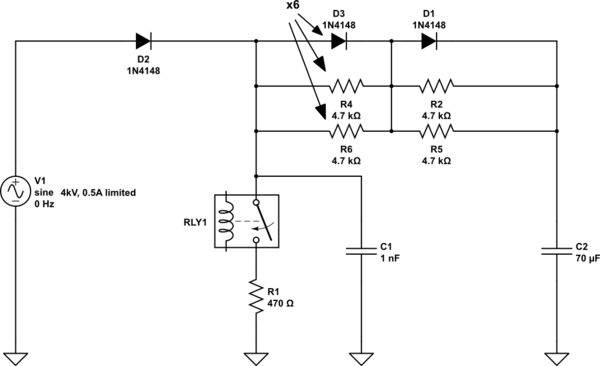
I am working with a high voltage relay (Cynergy3, DBT72410) to discharge a 70 uF capacitor charged to 4 kV using a string of resistors and a relay to ground. I have placed a resistor between one contact (low side) and ground. I am trying to decide if a capacitor connected between the other contact (high side) and ground is a good idea or not.

The thought process is as follows:

With the cap in place, the high side contact sits at whatever the main capacitors voltage is. So when it switches, the voltage difference between the contact and the signal is ~0. This will minimize arcing, but it produces inrush current which would be infinite without the low side resistor (it limits the current to about 8 A).

Without the cap, the high side contact is close to ground. So the voltage between the contact and the switched signal is the full cap voltage (up to 4 kV). This will eliminate the inrush current, but create arcs during the switch over.

Both are not good for the relay, but which is worse?

The power supply is off when the output cap (C2) is charged. The cap I am asking about is C1. During charge C1 is also charged to 4kV. When the relay closes, C1 is at 4kV, so the high side contact is also at 4kV, so no arcing. During relay chatter, the cap is continually recharged to the output cap voltage through the resistor stack (~60uS), as long as the open period of the chatter is greater than 60uS. This will continually keep the upper contact at the output cap voltage.

R1 always limits the current through the relay to no more than 8.5A. The carrying current of the relay is 2A, so inrush is limited to 8.5A for 60uS. Which I think the relay should handle with no problem.

\$\endgroup\$
6
  • \$\begingroup\$ I'm not entirely sure I understand you. But it sounds like you are trying to discharge about \$560\:\text{J}\$ of energy and you want to know if it is better to use a resistor to limit the current or if you should just directly short out the capacitor without a resistor to limit the current. I'm probably not getting that right. Could you clarify my confusion for me? \$\endgroup\$
    – jonk
    Commented Jun 24, 2020 at 20:59
  • \$\begingroup\$ Yes, I am trying to discharge 560J. No, the output capacitor (70uf) is connected to the top side of the relay through about 15k of resistance, always more limited. The cap I am asking about is a 1nF connected directly to the high side relay contact. It was put there to raise the contact voltage to the cap voltage when the relay is open. Since it is in parallel with the relay it will charge (through the same 15k and discharge directly into the relay/resistor. This was done with the intention of limiting arcing in the relay when the relay closes, since both points are at about the same voltage. \$\endgroup\$ Commented Jun 24, 2020 at 21:22
  • \$\begingroup\$ I guess I missed a lot. I think I understand the question better. But, now so, I also think it would not be hard for you to draw up the schematic using the existing editor that is available to you. Would you please add the schematic representation for your question? \$\endgroup\$
    – jonk
    Commented Jun 24, 2020 at 21:32
  • \$\begingroup\$ Yes I am confused and need a schematic. If 4kVDC, to resistor to contact, and 1nF across contact, to resistor to ground... the cap will charge to 4kV across open contacts. Perhaps something like the Ixys K0500LC600 can natively crowbar 6kV (975A RMS, 7kA non-repetitive) to ground, but it's pricey. \$\endgroup\$
    – rdtsc
    Commented Jun 24, 2020 at 21:43
  • \$\begingroup\$ I don't understand how the high side contact is "close to ground" when C1 is not present. \$\endgroup\$ Commented Jun 25, 2020 at 14:05

1 Answer 1

1
\$\begingroup\$

A schematic would really help here, but I don't think this will work. As long as the relay is open, no current flows anywhere (correct ?) that means no voltage drops over any of the resistors and hence you always will have the full 4 kV across the relay.

A capacitor in parallel with the load will just increase the load, a capacitor in parallel with any resistor will just discharge and a capacitor across the relay will just see the same voltage as the relay does.

\$\endgroup\$
2
  • \$\begingroup\$ The circuit in the schematic above works well. I'm curious if C1 is detrimental or beneficial. \$\endgroup\$ Commented Jun 26, 2020 at 14:11
  • \$\begingroup\$ I don't think that C1 does anything meaningful. Either way you have 4kV across the relay and either way, \$\endgroup\$
    – Hilmar
    Commented Jun 27, 2020 at 15:45

Your Answer

By clicking “Post Your Answer”, you agree to our terms of service and acknowledge you have read our privacy policy.

Not the answer you're looking for? Browse other questions tagged or ask your own question.