1
\$\begingroup\$

I have this Zener diode - 12V rated C part.

I just want to understand how to read the differential resistance column on table 8 for Zener current of 1mA and 5mA.

Suppose I give an input voltage of 16V across the 12V rated Zener diode. Let's assume that the series resistor is of appropriate value so as to focus on this understanding of the concept.

Let's also assume that the circuit is designed with proper series resistor for a certain load current.

My questions

  1. How to read the differential resistance column on the table 8 with respect to the working voltage column? Like when to use the 1mA zener differential resistance column value and when to use the 5mA zener differential resistance column value?

  2. For example, let us assume the 12V zener is in the breakdown region by applying 16V to the 12V Zener. What happens if I supply a Zener current of which is between the mentioned Zener currents in the differential resistance column of the datasheet , say for example a Zener current of 3mA or 15mA? How to find the Zener voltage when I supply these Zener currents?

  3. In certain Zener diode datasheets, they provide the minimum Zener current required to make the Zener enter into the breakdown region. But in this datasheet, no such minimum current is provided. Why have not provided and how to find the minimum current at which the 12V Zener will enter into the breakdown region if I have applied 16V?

\$\endgroup\$
5
  • \$\begingroup\$ Usually you would provide a voltage with series current limiting resistor to the zener, not the current. If you apply 16V to 12V zener it will probably blow as it would act like short circuit. \$\endgroup\$ Commented Jul 21, 2020 at 12:24
  • \$\begingroup\$ Yes. I understand that. But as I wanted to understand only the differential resistance concept, I mentioned that let us assume a series resistor is in place which will take care of a certain load current and can provide a zener current. What happens to the zener voltage value if I provide a zener current of 3mA and 15mA given that i provide a input voltage of 16V and a series resistor in place of an appropriate value to handle the above zener and load currents? \$\endgroup\$
    – user220456
    Commented Jul 21, 2020 at 12:33
  • \$\begingroup\$ If you have a series resistor that is appropriate for the load then the only way you can make the zener current different is by changing the 16 volt supply or by taking more load current. I'm confused by this question. I'm not sure what you are asking to understand. \$\endgroup\$
    – Andy aka
    Commented Jul 21, 2020 at 12:43
  • \$\begingroup\$ I just want to understand how do you interpret the differential resistance column on table 8. Could you please help me to understand that column. And when do you use the 1mA column and 5mA column under the differential resistance? You can also give your own example on how to interpret that differential resistance column \$\endgroup\$
    – user220456
    Commented Jul 21, 2020 at 12:45
  • \$\begingroup\$ You need to read this electronics.stackexchange.com/questions/352448/… and this electronics.stackexchange.com/questions/499523/… \$\endgroup\$
    – G36
    Commented Jul 21, 2020 at 13:04

2 Answers 2

1
\$\begingroup\$

You use the 1 mA column if you are intending to run your zener at a current of around 1 mA. You use the 5 mA column if you are intending to run your zener at around 5 mA.

For the 12 V BZX84 diode in the link you supplied, the typical values are 50 Ω at 1 mA and 10 Ω at 5 mA. That's a huge performance improvement, at the cost of power consumption, if you run at 5 mA rather than 1 mA.

So when designing your circuit, you have a choice. If it's to be battery powered, then you probably want to sacrifice performance for power consumption. If it's mains powered, and you can afford the extra heat dissipation in the space you have, you can get better differential resistance by running at 5 mA rather than 1 mA.

You would never apply 16 V to a 12 V zener. Or if you did, and the power supply had the current capability, it would fail in microseconds. You would use a resistor between the supply and the zener to supply it with a well defined current. You would get 1 mA though a 4 kΩ resistor, and 5 mA through a 800 Ω resistor.

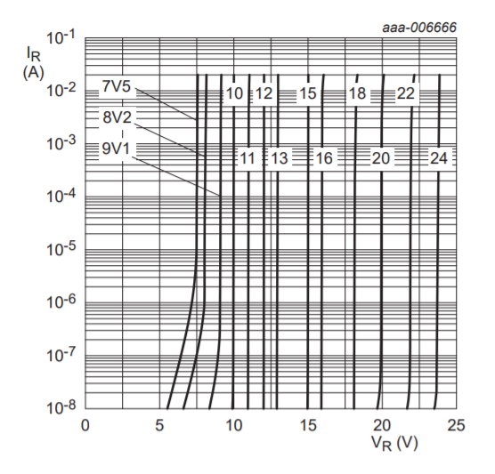
If you wanted to know the voltage to expect at 3 mA (with a 1.3 kΩ resistor), then you could have a go at interpolating the 1 mA and 5 mA voltages, using the curves of figure 6 to guide you. However, given the zener tolerance is around +/- 200 mV, and the temperature coefficient can be as high as 10 mV per K, there's little point in trying to be more accurate than 'about 12 V' when dealing with this class of component.

Figure 6 is also useful to answer your 'minimum current' question. It shows voltage versus reverse current for a number of diodes, the current plotted from 10 nA to 20 mA. The low voltage diodes <= 10 V and the high voltage diodes >= 18 V show a drop in voltage down at the 10 nA end. However, the intermediate voltage diodes, including the 12 V diode, show remarkably straight lines over the full current range. From this you can deduce that they need at least 10 nA to work. Of course their differential resistance will probably be very high at this current level.

\$\endgroup\$
4
  • \$\begingroup\$ Thank you very much for the answer. You answer pretty much answered my questions. Just a few doubts. Suppose I supply a zener current of 3mA which is exactly middle between 1mA and 5mA, which column should I refer & 2. And suppose if I supply 15mA, how to calculate the minimum and maximum zener voltage variation from the column \$\endgroup\$
    – user220456
    Commented Jul 21, 2020 at 14:00
  • \$\begingroup\$ And your last line you mentioned, their differential resistance will be very high at this current level. For the 12V part at the nA current range, it is a straight line. But how are you confirming that the resistance will be high? \$\endgroup\$
    – user220456
    Commented Jul 21, 2020 at 14:25
  • \$\begingroup\$ 3 mA is exactly the middle? Not really, it's the arithmetic mean, but for things like this we tend to use the geometric mean. However, it's somewhere between. Your least worst bet is to take a figure between the 1 mA and 5 mA figures. Given the tolerances on those figures, that is, the difference between typical and max, there is no point in trying to do this acurately. The best engineering statement is 'somewhere between 10 ohms and 50 ohms'. If I was interviewing, I'd mark down anybody who tried to be more precise. Zeners like this are not intended as precise references. \$\endgroup\$
    – Neil_UK
    Commented Jul 21, 2020 at 14:49
  • 1
    \$\begingroup\$ We see the diff resistance increases with a decrease in zener current. You may rest assured that it continues to increase further as the current continues to drop \$\endgroup\$
    – Neil_UK
    Commented Jul 21, 2020 at 14:50
0
\$\begingroup\$

ad 1)

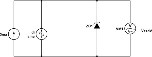
The differential resistance is:

\$r=\dfrac{dV}{di} \$

For a tiny change of current, there is a tiny voltage change all measured in the reference point which is Iz=3mA.

schematic

simulate this circuit – Schematic created using CircuitLab

ad 2)

enter image description here

As you may see the zener voltage won't change too much - the difference is so small that it can be seen on graph.

\$\endgroup\$
4
  • \$\begingroup\$ I am asking how to interpret the differential resistance column. Could you please provide an example on when you must consider the 1mA column value and when you must consider the 5mA column value \$\endgroup\$
    – user220456
    Commented Jul 21, 2020 at 12:46
  • \$\begingroup\$ @Newbie It's a part of diode characteristics, it is not an useful information if you have to calculate the use of the diode, it's more for test lab data. Also my schematics is useless for the diode end use, it is just a description of differential resistance. So, what you want to achieve, what is your real issue? \$\endgroup\$ Commented Jul 21, 2020 at 12:55
  • \$\begingroup\$ Just want to understand how to take the values and when to take the values from the differential resistance column \$\endgroup\$
    – user220456
    Commented Jul 21, 2020 at 13:00
  • \$\begingroup\$ Lower differential resistances means better regulation capability, more stable voltage. Of course there must be always a minimal current flowing through the zener, beyond the knee point. This minimal current is not available in the datasheet, but the graph shows a straight line from 10^-8 A for 12v zener, that's a very tiny current 10nA?? You have to calculate the series resistor such that when the load is maximal the minimal zener current remains and at no load condition, the zener current won't be higher than max. current. You place this working point to meet your demand . \$\endgroup\$ Commented Jul 21, 2020 at 13:30

Your Answer

By clicking “Post Your Answer”, you agree to our terms of service and acknowledge you have read our privacy policy.