11
\$\begingroup\$

This is a pretty basic question, as I'm still learning the fundamentals of electronics. I understand the analogy where amperage is compared to the quantity of water moving through a hose.

I have a 5V-2A power supply and I want to power my circuit. Each components' pins have different maximum currents (250mA for PIC, 180mA for the LCD, etc.).

Now if I'm following the above "water quantity" analogy, it should be OK for me to connect a component that draws max. 250mA because it draws from the 2A instead of the power source forcing the current into the pin. Now, I will have 1.75A of current left for the rest of my circuit.

Do I still have to put a resistor between the power supply and the VDD pin of a component? If yes, why?

(This question arised from when I learned that there should be an approx. 100 ohm resistor between the microcontroller's output pin and the LED. The LED's current rating was 25mA and the pins maximum output current was 25mA too and I didn't understand why we needed a resistor in between.)

\$\endgroup\$
0

2 Answers 2

14
\$\begingroup\$

To the first order...

You are correct. The load controls the maximum current that may flow, while the source controls the maximum voltage available.

but...

You are not correct about your LED. That's a different problem. Your thinking assumes, Ohm's law which assumes linear (and in-phase) operation.

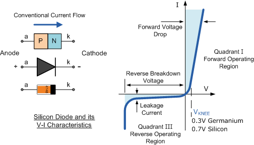
Diodes (including LED's) are non-linear devices. The Diode will present a constant voltage (approximately) when it is "on" independent of the amount of current flowing through it. The LED will be brighter with more current and burn-up (be destroyed) if too much current is allowed to flow through it for too long.

Notice how the line to the right of the y-axis in the figure is almost vertical. That implies that the voltage will change very little if the current through the diode changes a lot. V clearly does not equal IR for a diode.

enter image description here

Most discrete LED's in the microcontroller world hover around 2V at 20mA (varies by size, chemistry, and construction of the LED). If your microcontroller provides a 3.3V output through one of its general purpose pins (GPIO), then the current the LED demands from the circuit will exceed what the microcontroller can provide through its output pin and the internal resistance of the output driver in the microcontroller will limit the current to its maximum.

This will ultimately destroy the output driver of the microcontroller. To prevent this, a series resistor is added to limit the current explicitly to something safe.

You work backwards to size the resistor: (Vcc - Vled) / Iled = R

In most 3.3V microcontroller applications, the value turns out around 100 Ohms.

\$\endgroup\$
2
  • \$\begingroup\$ I see. What about adding a resistor between the pin and the LED makes a difference though? \$\endgroup\$
    – Ozbekov
    Commented Dec 22, 2012 at 0:51
  • \$\begingroup\$ You're welcome! =) \$\endgroup\$ Commented Dec 22, 2012 at 1:00
2
\$\begingroup\$

As a simpler analogy, different devices act differently. A microcontroller and most ICs are like small smart water pumps. They pull a small amount of water (current) needed and only that.

Leds on the other hand, are like dumb industrial strength vacuums. Connect it to a power source, and it will try to suck as much current as it can as fast as it can. That's why you need a resistor. A resistor is like a small pipe. It only lets so much current through due to it's size. It resists more than that current from going through. The led wants to pull as much as it can, but only the 25ma or so that you chose, gets through.

As for the why you need a resistor when both the led and the output pin are rated for 25ma, is because these are recommended current, not maximum or possible currents. A led works best at 25ma for (a trade off on brightness and how long it will last in thousands of hours), but can be driven by less current (not as bright, lasts longer) or higher current (brighter, doesn't last as long). Too little current and it won't turn on. Too much, and it will eventually burn out.

The output pin of your microcontroller is the same, but as a power source. Ideally, you only want to source 25ma of current from that pin (and this is without getting into total current from all pins, or voltage sag). 25ma in this case is the recommended operational current. You can source less as well. It's good practice to only source as much as you need for a given setup. You can source more as well. Most datasheets will list a maximum voltage and current for a given output pin. (For example, 25ma recommended, 40ma maximum). But because current is pulled, not pushed, you have to make sure that what you are building takes that into account. For signaling or communication between your microcontroller and a ic, there is probably no need since both will be designed not to pull too much current. But if you are hooking up a current hungry led, or transistor, or motor, etc, then you need that small pipe, a resistor, to make sure you keep it below the 40ma maximum.

Finally, just as a note, the power supply you are using works in the same exact way. Hook up something that draws more than the recommended/maximum 2A, and it will fry and break (or pop a fuse or go into a reset mode depending on how quality it is). Hook up a 2 amp high current led directly to it without a current limiting resistor, and both will not be happy. HTH.

\$\endgroup\$

Your Answer

By clicking “Post Your Answer”, you agree to our terms of service and acknowledge you have read our privacy policy.

Not the answer you're looking for? Browse other questions tagged or ask your own question.