1
\$\begingroup\$

I know how to subtract two single-ended voltages with an opamp configured as a subtractor.

I'm learning about fully differential signal processing and I'm wondering if it is possible to subtract two balanced fully differential signals without converting them to single-ended first.

Say I have two analog signals.

V1_D = V1_P - V1_N

V2_D = V2_P - V2_N

What I want is V3_D = V1_D - V2_D

By algebra this is V3_D = (V1_P - V1_N) - (V2_P - V2_N)

So, it looks like I could do it with three subtractor opamps. But would I run into a dynamic range problem?

Imagine I have a 5V VDD and my signals are rail to rail. So, V1_P - V1_N could be anywhere between 5 and 0. It doesn't seem to work unless I also scale the voltages down by 2. (which may be OK).

Is there an easier solution I'm missing here?

Thank you for your time.

\$\endgroup\$
2
  • \$\begingroup\$ It appears that your formulas do actually convert to single ended signals before the final subtraction. \$\endgroup\$
    – Andy aka
    Commented Sep 29, 2020 at 22:16
  • \$\begingroup\$ Yes, you're quite right. Is it possible to do it without ever converting to single ended? \$\endgroup\$ Commented Sep 29, 2020 at 22:28

2 Answers 2

2
\$\begingroup\$

enter image description here

This differential opamp computes a sum of differential signals, to turn it into a substractor simply swap the polarity of one of the differential inputs.

The opamp is a fully differential one like THS4131.

This assumes the source signals come from a low enough impedance to drive the resistors. If they are high impedance then you will need followers. This is the same issue as using a non-differential opamp in inverting mode, or as a substractor.

About the single opamp difference amplifier...

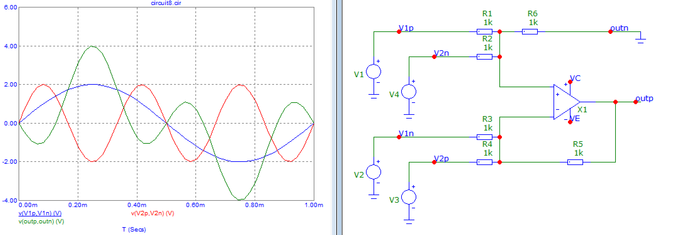
enter image description here

You can use it to turn a differential signal into single-ended, but if you add resistors you can also use it to add or substract differential signals. The output is single-ended, but... it is referenced to the node "outn", which as the name does not iply, is an input which is set at ground here. You could set it at another voltage.

Output is the voltage difference between outp and outn, which is actually a differential signal... albeit without some of the advantages, since positive and negative halves aren't symmetrical, thus it has half the voltage headroom, and won't cancel some distortion harmonics.

\$\endgroup\$
6
  • 1
    \$\begingroup\$ Beautiful, thank you! This is so simple! Thank you so much. I"ll try it out in LTSpice right now! \$\endgroup\$ Commented Sep 30, 2020 at 3:30
  • 1
    \$\begingroup\$ It is sweet how elegantly the topology compensates for the 1/2 attenuation in the input "summing divider" by the feedback gain of 2:1 - and all the resistors are the same value :-D (or so I hope). If the OP also wanted to involve proper termination of the input and output transmission lines, and keep overall transfer at 1.0, he would probably need more gain, at least for the output series termination. \$\endgroup\$
    – frr
    Commented Sep 30, 2020 at 5:10
  • \$\begingroup\$ Also note how the common mode component of the diff signal is removed after the summation. If the OP wanted, at the input, proper diff-mode termination and a higher common mode impedance against the reference GND, he would probably want a dedicated terminator resistor for each input line and larger values of the feedback resistors. And, use a dedicated differential op-amp per input channel, and do the summation after the common mode signal is removed = at their outputs. Perhaps the output divider could also serve as an output series terminator. \$\endgroup\$
    – frr
    Commented Sep 30, 2020 at 5:16
  • \$\begingroup\$ I'm wondering if the same effect could be achieved with a single op-amp, just by adding low-ohm input terminators and by using higher-impedance feedback resistors, including the input summing divider resistors... \$\endgroup\$
    – frr
    Commented Sep 30, 2020 at 5:18
  • \$\begingroup\$ @frr I'm struggling to understand what you mean re: removing the common mode component. Could you possibly make a schematic and add it as an answer? It seems like I would have an easier time visualizing it if I could see a schematic. \$\endgroup\$ Commented Sep 30, 2020 at 17:46
1
\$\begingroup\$

Maybe take a look at the THS4521. It's an op-amp with differential output - and it also has an extra input that allows you to set the center point for the diff output. So if you need to subtract two differential signals, how about... use two of these (or a single piece of the dual THS4522 - same datasheet), "normalize" each signal with one of these bros, and then subtraction is the same thing as addition of an inverted second operand, right? The summing operation could be done with two resistive dividers :-)

\$\endgroup\$

Your Answer

By clicking “Post Your Answer”, you agree to our terms of service and acknowledge you have read our privacy policy.

Not the answer you're looking for? Browse other questions tagged or ask your own question.