0
\$\begingroup\$

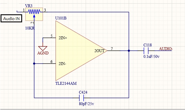
I want to understand the purpose of capacitors and variable resistor in the following audio amplifier circuit. Here is its datasheet.

C118 at amplifier output pin. C424 between amplifier input and output pins. VR3 between amplifier input and output pins.

Can we disconnect PIN3 of VR3 from PIN7 of Opamp? I cannot understand the purpose of this connection. PIN3 can be either left floating or maybe connected to ground to do volume control function through VR3. Please correct me if I am wrong here.

enter image description here

The power supply of the circuit is +/- 15 VDC.

Edit:

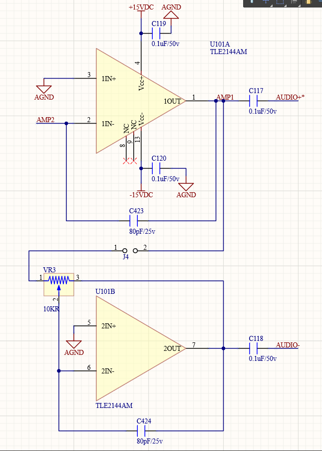
If the circuit include 2 stages and the first stage is without the feedback resistor as in following diagram then is it ok?

audio amplifier

In my second circuit diagram what is the meaning of 'Audio+' and 'Audio-' labels? Does it means that I can connect my mono headphones on these two points instead of using a 0 V (GND) reference for the headphones jack?

\$\endgroup\$
1
  • \$\begingroup\$ It's an op-amp and yes, pin 7 needs to feedback to pin 6 via resistor elements. \$\endgroup\$
    – Andy aka
    Commented Oct 28, 2020 at 10:24

3 Answers 3

2
\$\begingroup\$

No, it cannot be disconnected, because resistance between op-amp output and inverting input is the feedback resistance that sets the gain of an inverting op-amp in conjunction with the input resistance.

So that's a volume setting pot, and disconnecting pin3 would remove feedback and the circuit would not work.

\$\endgroup\$
4
  • \$\begingroup\$ I have added more details in the post about another stage in the circuit without feedback resistor. Will it work this way or not? \$\endgroup\$
    – scico111
    Commented Oct 28, 2020 at 10:42
  • \$\begingroup\$ No, because there is no feedback \$\endgroup\$
    – Justme
    Commented Oct 28, 2020 at 11:17
  • \$\begingroup\$ In my second circuit diagram what is the meaning of 'Audio+' and 'Audio-' labels? Does it means that I can connect my mono headphones on these two points instead of using a 0 V (GND) reference for the headphones jack? \$\endgroup\$
    – scico111
    Commented Oct 29, 2020 at 4:35
  • \$\begingroup\$ If the circuit was correctly designed and had correct component values, yes it could be done so, but I don't see the point why connect it like that and simply use ground for headphones directly. Maybe if you told why it might make sense. \$\endgroup\$
    – Justme
    Commented Oct 29, 2020 at 8:35
1
\$\begingroup\$

Neither circuit will function as a traditional audio amplifier.

With the pot in place and connected, the circuit is a traditional inverting amplifier. The pot replaces the two resistors that set the gain of the circuit. As you turn the pot, both resistor values change; this varies the gain of the circut. The 80 pF capacitor is there to decrease the gain at very high frequencies. This reduces noise in the output signal.

Without the pot, the circuit is basically an opamp running open-loop, with no negative feedback to stabilize its gain. The capacitor acts as an integrator, but its time constant is so small that it barely affects operation. The output signal will be very very distorted, basically turning the audio signal into square waves.

https://en.wikipedia.org/wiki/Operational_amplifier_applications#Inverting_amplifier

\$\endgroup\$
3
  • \$\begingroup\$ what can be minimal changes in this circuit to make it work as basic mono audio amplifier? \$\endgroup\$
    – scico111
    Commented Oct 28, 2020 at 11:20
  • 1
    \$\begingroup\$ That's a different question to that at the top of the page. Start with specification: (1) What is the input signal level? (2) What is the required output level? (3) What is this circuit feeding into? (Impedance may be significant.) (4) What bandwidth do you require? (5) Why do you think you need two stages? Try to address each point in your question. \$\endgroup\$
    – Transistor
    Commented Oct 28, 2020 at 12:14
  • \$\begingroup\$ My audio input is analog, centered at GND level and max 0.5 V peak-peak signal. I want to amplify this signal so that I can listen it on my simple (no built-in amplifier) headphones. I think an op-amp inverting amplifier gain of 50 would make it audible on headphones. I will remove 1 stage from the above circuit and use only U101B for amplifier as Inverting Amplifier. Please correct me if am wrong in this understanding. \$\endgroup\$
    – scico111
    Commented Oct 28, 2020 at 12:46
1
\$\begingroup\$

Your circuit with the pot is almost a classical Baxandall volume control, the nice feature being semi reasonable behaviour with a linear pot, but it really wants some resistance in series with the input end of the pot to set maximum gain.

U101 is just nonsense unless you want a very short time constant integrator, I would use it for the other channel of the audio.

C424 provides high frequency feedback to help stabilise the opamp against the effect of stray capacitance from the inverting node to ground, which will otherwise cause reduced phase margin at high frequency.

C118 is the output DC block and would want to be way larger for a headphone application, you would want a few tens of microfarads with maybe 20R in series with it for cans.

You will also want a dc blocking cap in series with the input to the opamp, and will need to respect the fact that the input impedance depends on the setting of the pot.

This is however REALLY the wrong thing to use as a headphone driver.

\$\endgroup\$

Your Answer

By clicking “Post Your Answer”, you agree to our terms of service and acknowledge you have read our privacy policy.

Not the answer you're looking for? Browse other questions tagged or ask your own question.