I am researching the PI filter. There're a number of great articles on how to calculate values for inductor and capacitors, the response curves and frequencies. Examples are: Input Filter Design for Switching Power Supplies, Ferrite Beads Demystified, Optimal Single Resistor Damping of Input Filters etc etc.
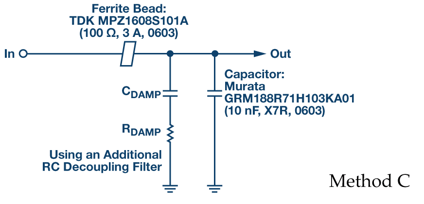
The circuit below works great, suppressing the ringing during fast power supply voltage rise.
 I will not include simulation pics as it is fairly easy to draw and simulate it.
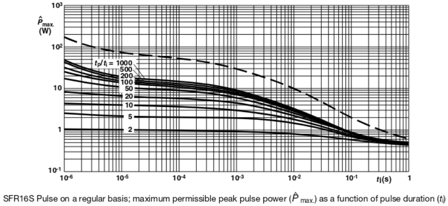
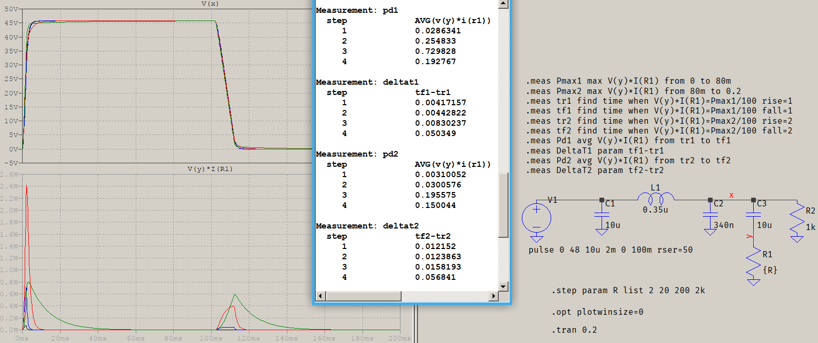
However I can not find any information on the damping resistor power rating. The steeper voltage rise, the higher immediate current flows through the resistor while its series capacitor is not charged. Taking damping resistor as 2 Ohm, it will anyway be much larger than tantalum cap or MLCC ESR, thus during power on most power will be seen on the resistor. I simulated it to be up to 45 Watt...
L2 is a ferrite bead BLM21PG221, consider it working in its inductive region. (however during fast transients, including power on, may it be more capacitive/resistive rather than inductive?)
The only statement about damping resistor current I found in third source I cited:
Capacitor Cd blocks dc current, to avoid significant power dissipation in R.
Yes, in static it is. But I am sure people also considered dynamic performance - in particular during power on.
So what do I miss here and what would be the power rating on the damping resistor?
There's a second question, very closely coupled with the above one: what is practically achievable power rail rise time? The answer to this question will define the answer to former one. Yes, ATX power supplies have strict standard on the power level rise time, what about other type of power supplies (switching and AC-DC)? What about turning switch on closing the circuit, theoretically happening in a nanosecond causing very sharp rise time? Does the first capacitor on the power wire path makes a difference "absorbing" the initial voltage strike?


