0
\$\begingroup\$

I am designing an opamp based linear regulator for educational purpose.Please find the attached image. enter image description here
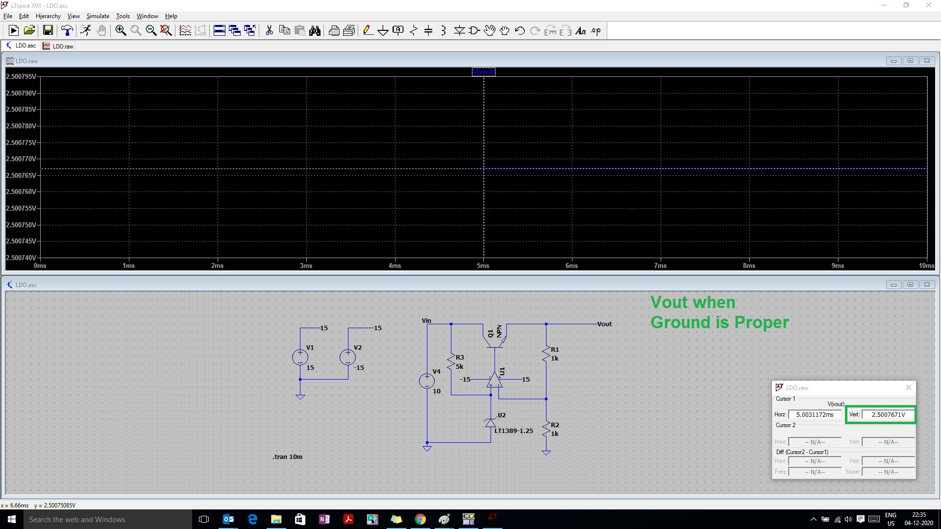
I know that due to negative feedback voltage at the both terminals of the opamp will be same and is equal to Vref .Here it is 1.25V and Vout=Vref(1+R2/R1) and I obtained the proper 2.5V at output.

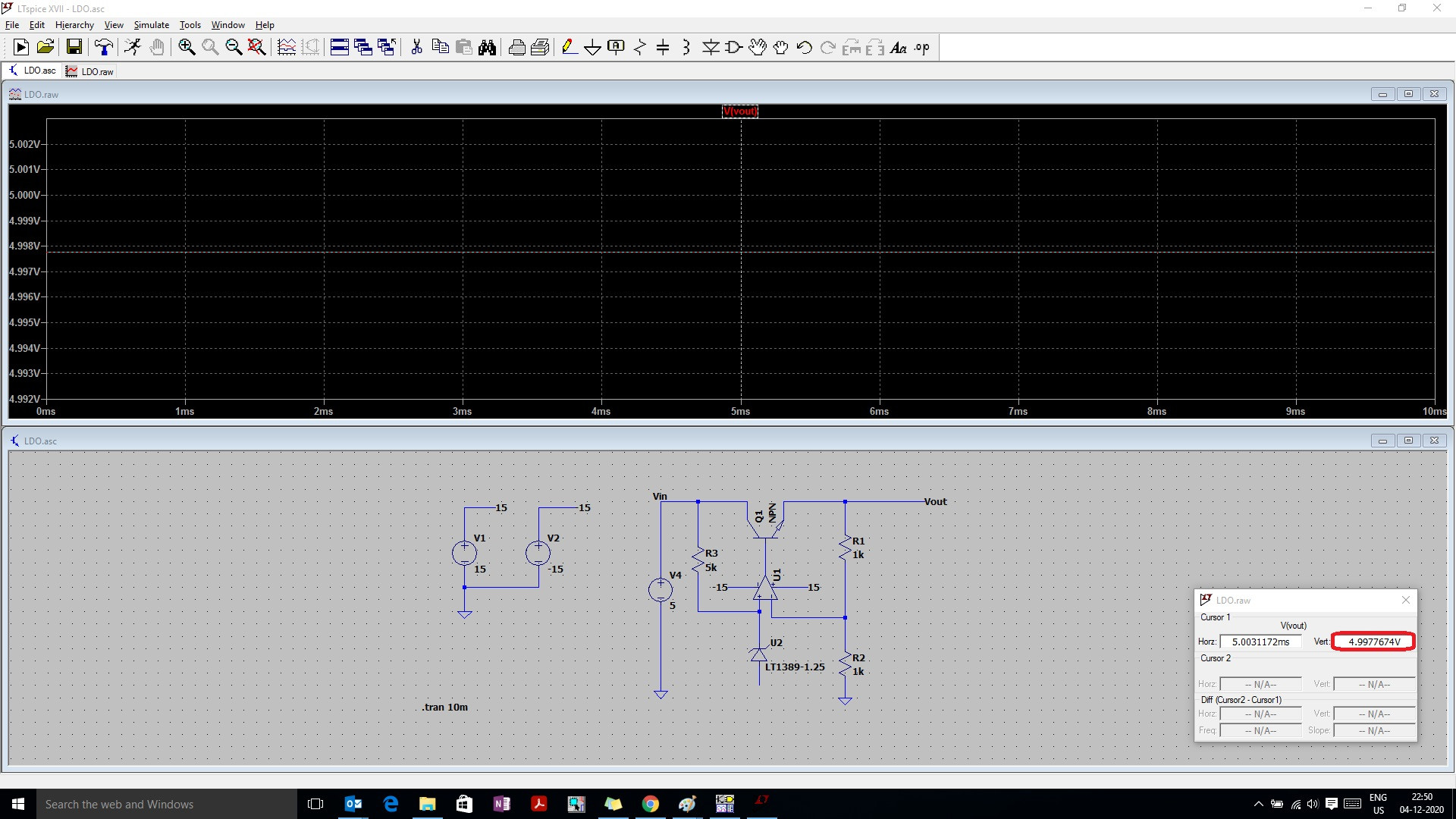
Now I removed the refernce and Vin(5V) is directly connected to Opamps non inverting terminal. enter image description here At this time the output obtained is 5V only as per the equation it shoud be 10V.May I know why I am not getting 10V at output.Please tell me where I went wrong in understanding the circuit.
\$\endgroup\$
0

3 Answers 3

1
\$\begingroup\$

May I know why I am not getting 10V at output.

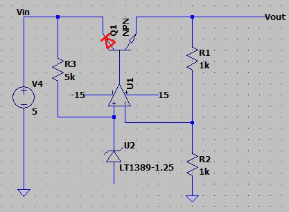
You are not getting anything higher than 5 volts at the output because although the op-amp is powered from a positive supply of 15 volts, its output is clamped by the now forward biased base-collector region of Q1. See below and the little diode symbol I've added in red; it will limit U1's output to about 5.7 volts and, of course, that becomes about 5 volts at the emitter because both PN junctions in Q1 are forward biased: -

enter image description here

If you disconnected the collector from the circuit you should then see 10 volts at the output but, it's not much of a power regulator like this of course. If the 5 volts at the input (Vin) were sourced from a bridge rectifier (as per many supplies) then the bridge rectifier would get reversed biased due to the action of the red diode and the op-amp output would be able to lift the collector voltage with the outcome being that emitter would become 10 volts and hit the regulation target.

\$\endgroup\$
3
  • \$\begingroup\$ Thanks for the answer.Here still negative feedback exixts,but may I know why opamp is not able to make it's both input equal. \$\endgroup\$
    – Confused
    Commented Dec 5, 2020 at 3:23
  • 1
    \$\begingroup\$ The op-amp output is prevented from rising to 10.7 volts due to the internal collector-emitter diode becoming forward biased and clamping the collector to about 5.7 volts thus the emitter is about 5 volts also. Try disconnecting the collector and see how it will come into regulation. \$\endgroup\$
    – Andy aka
    Commented Dec 5, 2020 at 10:00
  • \$\begingroup\$ Perfect answer , thanks so much. \$\endgroup\$
    – Confused
    Commented Dec 5, 2020 at 10:19
1
\$\begingroup\$

If I understand correctly, \$V_{IN}\$ is 5V. \$V_{OUT}\$ will never be more than \$V_{IN}\$ in your circuit.

\$\endgroup\$
1
\$\begingroup\$

For the second circuit, change the input V4 to 6 V. The output probably will go to 6 V. this is not because the circuit is functioning at unity bain. It is because the circuit output is saturated.

To see what is going on, delete U2 and replace it with a 1.2K resistor to GND. Leave R3 in place. Now the opamp input is approx 1 V, and the output should go to 2 V.

\$\endgroup\$

Your Answer

By clicking “Post Your Answer”, you agree to our terms of service and acknowledge you have read our privacy policy.

Not the answer you're looking for? Browse other questions tagged or ask your own question.