0
\$\begingroup\$

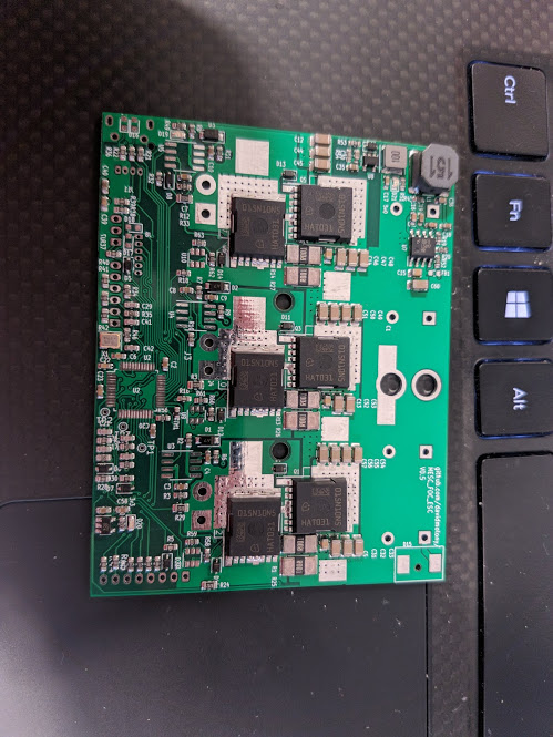
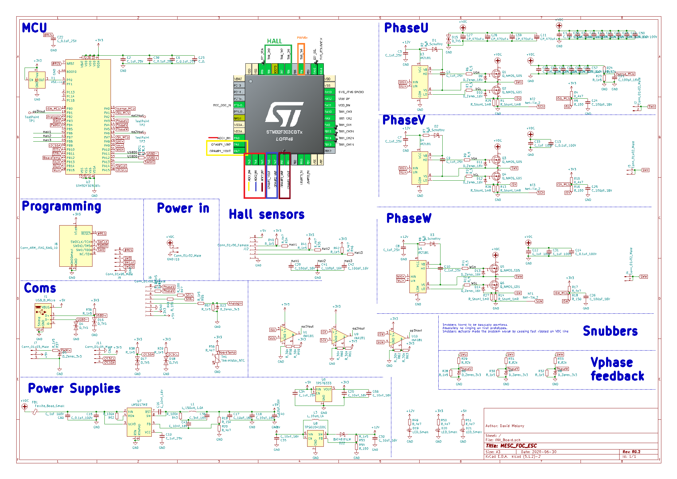
I have an STM32L433, fresh from RS components. I soldered it to my board. PA6 is connected to the output of an opamp - INA181A1.

There are another 2 INA opamps on the board, connected to other pins.

I have now had 2 INA181s die (actually I am not sure they died, since I unsoldered the first and replaced it assunming it was broken... the second I unsoldered just the output leg and may have damaged it mechanically...). The board is not even programmed yet. There is actually not yet even a programming header...

The net between the opamp and the MCU is pulled high. If I hold the MCU in reset state (connect the debug header nRES to ground) the opamp-MCU net floats. As soon as I release the reset pin, it pulls high.

The other 2 channels to not do this! The other 2 channels behave exactly as expected!

There is no board error. There is >500kOhms between the net and ground/3v3 when not powered - this pull IS coming through the MCU. I observe there is ~50mA extra drawn from my power supply between when the MCU is held in reset and when reset is released.enter image description here
Are my new chips pre programmed???am I missing some line in the datasheet/reference that says "PA6 will pull high when new"?

The boards were supplied without MCU and opamps and gate drivers. I have populated them myself. I have built 2 boards with F303CB chips, which work fine, using internal opamps, and 1 with L433CC. The pinout appears to be the same in terms of power, boot0 etc.

The schematics can be seen in https://github.com/davidmolony/MESC_FOC_ESC/tree/Rearrange_Vin - this is an open source EBike controller I work on in the evenings. I have been riding around with the F303CB version, pushing ~80phase amps and getting up to ~40km/h, so the board DOES work. Edit: Schematic Schematic Offending opamp is op2, U9
\$\endgroup\$
8
  • 1
    \$\begingroup\$ Can you link schematic and circle offending Op Amp or INA \$\endgroup\$
    – D.A.S.
    Commented Jan 15, 2021 at 14:21
  • \$\begingroup\$ Most MCUs default to GPIO pins as INPUT and they generally float HIGH and may even have an internal pullup enabled. what are you expecting them to do at power-up? \$\endgroup\$
    – jwh20
    Commented Jan 15, 2021 at 14:28
  • \$\begingroup\$ Well, if it aint active out of reset, simply single-step through the code until you find the culprit. This sounds very likely to be a software bug. Or alternatively, you left some mode selection pins floating in the hardware design that should have been tied to Vdd or ground. Silicon bugs is far less likely though make it a habit of always reading through the published errata. \$\endgroup\$
    – Lundin
    Commented Jan 15, 2021 at 14:40
  • \$\begingroup\$ Lundin, as stated in the original question, MCU is not programmed \$\endgroup\$ Commented Jan 15, 2021 at 14:42
  • \$\begingroup\$ @DavidMolony Ah, my bad. Well then you can rule out software for sure :) \$\endgroup\$
    – Lundin
    Commented Jan 15, 2021 at 14:44

2 Answers 2

4
\$\begingroup\$

If the MCU is unprogrammed, it will automatically go to factory bootloader.

Bootloader uses PA6 as SPI1_MISO, which will be push-pull output.

It might go high-impedance if PA4 used as SPI1_NSS is pulled high, so that is something you might try, but not much else.

\$\endgroup\$
5
  • \$\begingroup\$ I did just note this st.com/resource/en/application_note/… could be the issue. You reckon this is the case? Not sure what to do about that :S PA4 is always pulled low, since it is used as a phase voltage detection, with potential divider to ground. \$\endgroup\$ Commented Jan 15, 2021 at 14:41
  • \$\begingroup\$ TBH justme, this looks like the most likely culprit. I shall have to think about how to manage this one. I did not consider this atall, since I merely as an afterthought dropped a different pin:pin compatible MCU on; I want to try porting my code. \$\endgroup\$ Commented Jan 15, 2021 at 14:44
  • \$\begingroup\$ I have pulled PA4 artificially low on reset, by jumping the 5V and the PhaseV together on the J6 header. As Justme says, PA6 then has different behaviour... it appears to pull low, but this might be high impedance... it certainly makes a difference, and I am thus inclined to take Justme's explanation. \$\endgroup\$ Commented Jan 15, 2021 at 14:52
  • \$\begingroup\$ Jump wire it to another pin to see if there are other errors, and fix the errors in the next PCB. Meanwhile, you can build the board without the opamp, and program the MCU, then solder the opamp on - but never let the MCU reboot when erased. You can also remove USB data pull-up, the MCU has one built-in, so there is now extra pull-up which signals the PC that the device is ready for enumeration even if it is not. \$\endgroup\$
    – Justme
    Commented Jan 15, 2021 at 14:54
  • \$\begingroup\$ I intend to use f303, this is built just as an experiment with software porting. If it turns out the L433 works much better I might switch, and then I'll deal with it. A simple solution for the next rev I just thought of is to put a ~150ohm resistor between MCU and opamp, then they can sit and push 1.6V/150ohm = 10mA into each other all day long. \$\endgroup\$ Commented Jan 15, 2021 at 14:57
0
\$\begingroup\$

An aside: I made that sort of a mistake at one point and the lesson is that you must avoid connecting an opamp output to anything without a series resistance. That resistance may be already present for functional reasons and then you wouldn’t add it, of course. And sometimes the function of the circuit may preclude it. But generally it’s a bad idea to just hard-connect an opamp output to any input pin. It gets very hard to debug opamp circuits without such resistors, and sometimes the lack of resistance may cause latch-up-like behavior - not an actual SCR latch-up, but the circuit may start in a “nonsensical” operating point and stay there because with no series resistors large currents may flow from the output, that would never be present in normal operation, and an undesirable steady state is entered which will persist until power-down.

I had this problem when somehow the baord vendor put a bunch of dodgy chips on the board - they didn’t look like fakes, but more like packaged dies that passed die test and “died” in packaging. Those were double op-amps where only one op-amp would work, but with the circuits being connected hard, you couldn’t tell which ones were the source of the problem and which ones were misbehaving just because of incorrect inputs.

Many op-amps will misbehave when input currents are too high, eg. because there’s a diode clamp between the inputs. MCUs can also misbehave then, especially if you manage to overheat the pin driver/mux and eg. its performance degrades. Say that the opamp output goes to an ADC input. I have experienced several mainstream MCUs where a short circuit current from an op-amp (or any other source of similar strength) will degrade the ADC mux at high ambient temperature and the ADC performance will be poor or even none (stuck at 0 or FS). This is usually precipitated by a pin conflict just like you experienced.

\$\endgroup\$

Your Answer

By clicking “Post Your Answer”, you agree to our terms of service and acknowledge you have read our privacy policy.

Not the answer you're looking for? Browse other questions tagged or ask your own question.