-3
\$\begingroup\$

Disclaimer: I’m computer scientist

I would like to generate an "intense" varying magnetic field by connecting a coil to a max 160W audio amplifier. The theoretical output frequency range is 20Hz to 20kHz. I plan to only output sinusoidal signals in the range 500Hz to 5000Hz.

The audio amplifier I have to do that is a 4Ω SMSL SA 98E 2x160W specifications in french, less detailed specifications in English from the manufacturer.

I would like to know what should be the optimal inductance of the coil I should use and the wire thickness.

I have so far tried a 0.5mH coil with 0.5mm wire, but the coil heats which indicates that the wire is too thin. 0.5mH is ~4.4Ω at 1kHz.

What is the most unclear to me is the 4Ω impedance required by the amplifier. At what frequency should it be 4Ω ? I could not find a clarification on that with google. But I did find plenty of warnings that it can harm the amplifier if the impedance of the HP is too low.

Since I don’t want harm my amplifier, I ask the experts here if the 4Ω impedance should be at 1kHz or 20kHz. In the later case the inductance of my coil should indeed be much lower.

Edit 1: as asked by StackExchange I must clarify why this question is different from this similar question. The titles are very close, but I initially badly formulated my question which ended on a different topic (measuring inductance). Tony Stewart Sunnyskyguy EE75 did provide a precise answer to the question in the title but I was unsure if it was safe for my amplifier. This question is now more on topic and ask about the risk for my amplifier to use a low inductance. I apologise for the inconvenience.

\$\endgroup\$
9
  • \$\begingroup\$ I already showed you an impedance chart of L vs f and a magnetic core will boost the B field in mT. Wire in a loop has a certain nH/mm value and uOhm/mm resistance while heat loss is due to R alone and frequency response is limited by L/R=T time constant \$\endgroup\$
    – D.A.S.
    Commented Jan 19, 2021 at 13:57
  • \$\begingroup\$ Ideally, your amplifier would "see" 4 ohms all across the frequency range. A simple coil can only do that if it has significant resistance - which will get hot when you push a lot of power through it. \$\endgroup\$
    – JRE
    Commented Jan 19, 2021 at 14:01
  • \$\begingroup\$ @TonyStewartSunnyskyguyEE75 you didn’t answer my questions and there is no reference for the graph. So I don’t know if it applies to my use case. I ask here if there is no risk to harm my amplifier the if 4 Ω impedance is at 20kHz, which implies the impedance at lower frequencies will be much lower. \$\endgroup\$
    – chmike
    Commented Jan 19, 2021 at 14:04
  • \$\begingroup\$ @ElliotAlderson this is the question I asked and the answers I got don’t fully answer my questions. I tried to reformulate my question in a much more concise and precise way. \$\endgroup\$
    – chmike
    Commented Jan 19, 2021 at 14:06
  • \$\begingroup\$ If your original question had problems then you should fix the original question. Asking a new, very similar, question leads to people duplicating their effort in writing a good answer. It's considered bad manners here. \$\endgroup\$ Commented Jan 19, 2021 at 14:07

4 Answers 4

1
\$\begingroup\$

Your amp has a max output current of 10A (datasheet) and a peak output voltage of 36V.

36V peak is 25V RMS, so if you want 10A into the load that's a maximum impedance of 2.5 ohms, which corresponds to an inductance of 80µH.

Adding a bit of safety margin, let's say 100µH.

Of course, at 500Hz, the inductive part of the impedance will be 0.25 ohms, so you won't be able to use full power or the current would simply be huge. But that's a class D amp, which means it has no Safe Operating Area restrictions for the output transistors, which means you don't have to add a resistor in series or do anything special for this extremely low load as long as the output voltage stays low enough to not exceed the maximum current.

So what you could do is just wire enough turns for 100µH, then set the voltage on the signal generator to have the AC current you want in your coil. This means you must set a voltage that is proportional to frequency.

Pros: you always get the same current in the coil no matter the frequency, and you don't have to add a resistor in series to waste power.

Cons: it's a bit more complicated since you have to adjust signal amplitude.

\$\endgroup\$
10
  • \$\begingroup\$ Sorry of my ignorance, but if at 500Hz the impedance is 0.25Ω, is there a risk that the current will be very high and the coil heats too much ? Or will it be limited by the power source. I forgot to specify it, but I need to produce this varying magnetic field for 10min. Here is a ready made coil that I could use. It has a 1mm wire and is 100 μH. Is the wire too thin ? \$\endgroup\$
    – chmike
    Commented Jan 19, 2021 at 15:17
  • \$\begingroup\$ I=V/Z, so you should use an amplitude that corresponds to the current you want. What value of current do you want? \$\endgroup\$
    – bobflux
    Commented Jan 19, 2021 at 15:50
  • \$\begingroup\$ It can’t be 10A because my electric cabling will melt. Does 4A seam reasonable ? Sorry about my ignorance. Electricity is not my competence. Let assume 4A. It don’t have a precise specification of the magnetic field intensity, it’s just the reasonably stronger I can produce. \$\endgroup\$
    – chmike
    Commented Jan 19, 2021 at 15:57
  • \$\begingroup\$ It has 0.12 ohm resistance so at 4A RMS it will dissipate about 2W (P=RI^2), considering the size (it's huge) it should get a bit warm to the touch, no problem. \$\endgroup\$
    – bobflux
    Commented Jan 19, 2021 at 16:01
  • \$\begingroup\$ Ok, I’ll try it. It’s not that expensive. Thank you very much. I’ll reduce the power if needed. The one with thicker wire has a too small internal diameter for my need. As Andy Aka said, if it is properly rolled up the magnetic field is stronger. \$\endgroup\$
    – chmike
    Commented Jan 19, 2021 at 16:05
2
\$\begingroup\$

I would like to know what should be the optimal inductance of the coil I should use and the wire thickness.

Generally speaking a 4 Ω speaker load will have a DC resistance that is about 3 Ω. This is from tests I conducted many years ago on 8 Ω speakers; they tended to average out at 6 Ω DC resistance. OK that's my limited scope on what sort of impedance might be presented to an amplifier by the load of the speaker.

Based on my limited experience, I suggest that you have an external 3 Ω resistor (that will generate the heat) and wind the coil with thicker wires (in order to reduce the winding resistance) and aim for 0.5 mH as per your original design aim. However, if you think you might need more inductance then you might be on a slippery slope...

Inductance is proportional to turns squared (if all the turns couple to each other) whereas inductance is proportional to just turns (to the power 1) if there is no coupling. How to figure out the amount of coupling is difficult but, maybe aim for something a bit closer to 2 than 1 as the power.

I mention a slippery slope because as you add turns to get more inductance, for a given drive voltage and frequency, the current falls because the impedance has risen. However, inductance isn't the primary factor for magnetism; it's ampere-turns that create a stronger magnetic field, so in some respects, having a few turns of thick wire connected via a step down transformer to your power amplifier may be better.

For instance, a 4:1 step-down transformer connected to a load of 0.25 Ω (reactive) will look like 4 Ω to the amplifier terminals. But, it's difficult to guess what might be best for you; I'm just suggesting some options to try and boost the magnetic field.

Having said all of that, I would still have an external fixed value 3 Ω resistor feeding the inductor directly (or the transformer).

\$\endgroup\$
2
  • \$\begingroup\$ What do you mean by coupling of the turns? Do you mean that turns are sticking in the most compact form ? So if I make a very compact and clean coil, the magnetic field will be stronger than if the turns are a bit more chaotic ? \$\endgroup\$
    – chmike
    Commented Jan 19, 2021 at 14:50
  • 1
    \$\begingroup\$ Yes, if they are closely packed in defined layers, the coupling would produce a power close to 2. The most optimum cross section is a short coil with layers producing a total layer height that is about the same as the coil length. \$\endgroup\$
    – Andy aka
    Commented Jan 19, 2021 at 14:57
2
\$\begingroup\$

I understand you want to make an "intense" field, so, absent any other specifications, I interpret that to mean 'stronger than the one you have at the moment'.

How do you make your existing field stronger?

  • less airgap

Does your existing coil have any air in the path that could be ferrite. If it's a solenoid, then can the return path be made to be ferrite? Halving the length of the air path round the winding will double the H field and so B field across the remaining airgap.

  • more current

You can't get more current from your amplifier. 160 W at 4Ω comes out to about 6 A rms, and bobflux has found the datasheet gives 10 A, which is consistent with that. The amplifier recommended load resistance is simply a way of limiting the output current, given that the voltage is automatically limited by the power supply.

But, at a particular frequency, you can resonate the coil with a capacitor, to increase the coil current to many times that of the amplifier output. If you had a selection of specific frequencies, and a box of capacitors with a switch, the changeover could be very quick.

  • lower duty cycle

How can you tolerate the extra coil current? It doesn't matter if a coil of copper gets hot, it only matters if it gets too hot. Let it cool down between pulses, and you can safely use a single massive pulse that heats it to maximum temperature in milliseconds. It's quite easy to calibrate the I2t of a load, which is the adiabatic heating it can tolerate.

\$\endgroup\$
1
  • \$\begingroup\$ Thank you for your answer. I would prefer I could change the frequency freely with a generator. So I’ll have to give up on second proposal. For the last point, I must be able to generate the "intense" varying magnetic field for 10min for instance. Sorry that I didn’t specify that. So heating appears to be a significant problem, but I agree with your point. Do you think that a ⌀1.5mm wire would be enough ? I didn’t manage to find thicker yet. \$\endgroup\$
    – chmike
    Commented Jan 19, 2021 at 15:04
1
\$\begingroup\$

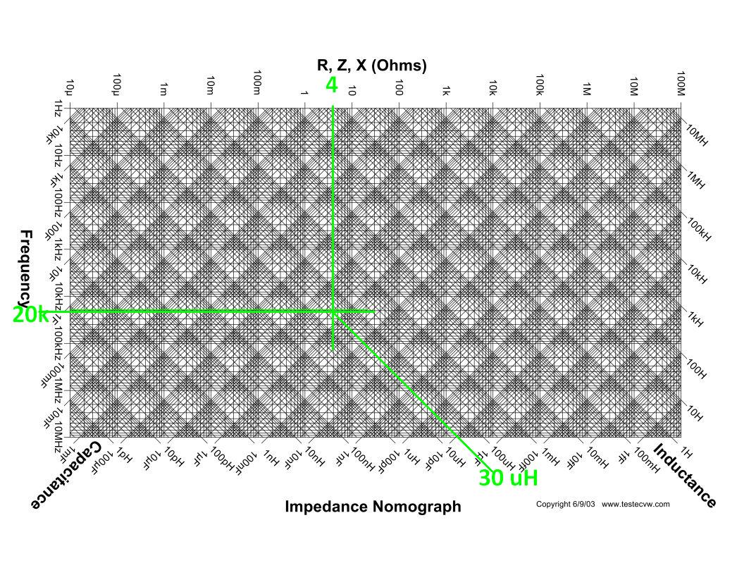
enter image description here 4 Ohms = 20kHz @ 30uH

For 2kHz use 300uH but wire resistance should be capable of dissipating x% of total power output such as 1% of 100W=1W to keep cool.

Since you used 0.5mm wire = 4.4 Ohms you lost about half the power in heat, so to achieve 1% of 4 OHms the radius must increase 10x for 1% of 4.4 Ohms and about same length of wire. L will vary due to geometry of radius and height as well.

The L/R =T ratio also defines the upper frequency limit or rise time to T=64%

R is a choice of heat dissipation and ability to cool it affect temperature rise by thermal conduction and not insulation.

\$\endgroup\$
2
  • \$\begingroup\$ I understand the principle of the graph. If I use a 30μH coil that would yield a 4Ω impedance at 20kHz, the impedance will be much lower if I generate a signal well below 20kHz, like 1kHz for instance. Is there a risk that it harm my amplifier ? \$\endgroup\$
    – chmike
    Commented Jan 19, 2021 at 14:39
  • \$\begingroup\$ Your amplifier can handle 1 Ohm but it will start to get hotter at full output but not reduced output at same current, as it has a 10 milliohm drive impedance roughly. Now follow my instructions \$\endgroup\$
    – D.A.S.
    Commented Jan 19, 2021 at 15:42

Not the answer you're looking for? Browse other questions tagged or ask your own question.