Background
I'm designing a power amplifier and I want to sense power-drops early, in order to properly shut down the class-D amplifiers, SMPS's and save status in the microcontroller, before brownout occurs. In order to do this, I'd like to rely on AC mains sensing with an AC-input opto-coupler.
I could do this in a very simple way, by adding appropriate series resistor(s) to the LED's, but with about 2mA that consumes about 0.5W permanently. Hence I'd rather rely on a capacitive voltage drop.
The 'problem'
I'd like to protect this sensing circuit from the nasties that come from the mains power line. So, I've looked at the surge behavior of several components involved:
- opto-coupler (SFH6206): 2,5A surge, check
- X2 safety series capacitor (TDK B3293 47nF): OK for series operation, this is however the problematic part for surges.
- series resistor (Panasonic ERJP08 ): 10k resistor should be able to endure 160V during surges.
- TVS diode across opto-coupler and series resistor (Littlefuse 8.0SMDJ100CA): can absorb enough power and clamps to appropriate voltages with regard to the other components.
My questions
In normal operation, the below schematic, using the components enlisted above, behaves just fine and will be reliable. I am however hesitant when it comes to power line surges.
First of all, what exactly is a power line surge for this type of domestic, consumer type device for indoor use. I've seen most references suggesting a 8/20µs peak with a top of 6kV, I've however also seen documents suggesting a 0.5µS rise and 6kV peak, with 100kHz decaying oscillation waveform, with a 60% decay between the first and every following positive or negative peak. I'd like some guidance from knowledgeable people here.
It also seems that any thermal fuse or circuit breaker will react much slower (in about 10ms), so any surge damage will occur before mains power is cut off. Correct?
Last problem, assuming I have to consider the 8/20µS 6kV peak, how will this affect the X2 capacitor. It is certainly out of specs. But looking at X2 safety capacitors, pulse types are not recommended for series operation and types for series operation do not withstand surges very well.
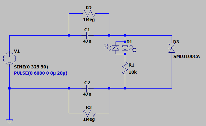
Below is the simulated schematic.
During the surge, I observe the following peak values in the simulated circuit:
- D3 clamps at 144V/18A, peak power of 2.5kW, this is OK.
- R1 clamps at 141V/15mA, this is OK
- C1 and C2 conduct 18A while rising up to 2.9kV with a peak power of 49kW, this is problematic, I think.
So my additional question is: can this be improved upon or should I accept that the capacitor will suffer and self-heal? And if it does, will it be fit for further use? It's capacitance will drop, current through the opto-coupler will be affected, but by which order of magnitude can I expect degradation?
As a last note, I can imagine that a series protection device can protect the X2 capacitors. But which type of device should that be, it should be able to absorb enough energy, it should act fast and it should have low resistance in normal operation.

